编带机说明书-含图纸ttm402.pdf - 第62页
3-20 TM-403 User’s Guide Taper Tab D292105.6a.fm 4. Pressing the right Arrow button in the third T aper Setup screens opens the final Ta p e r Setup screen. The fourth T aper Setup screen focuses on Leader and Sensor set…
D292105.6a.fm Taper Tab
Chapter 3: Human Machine Interface 3-19
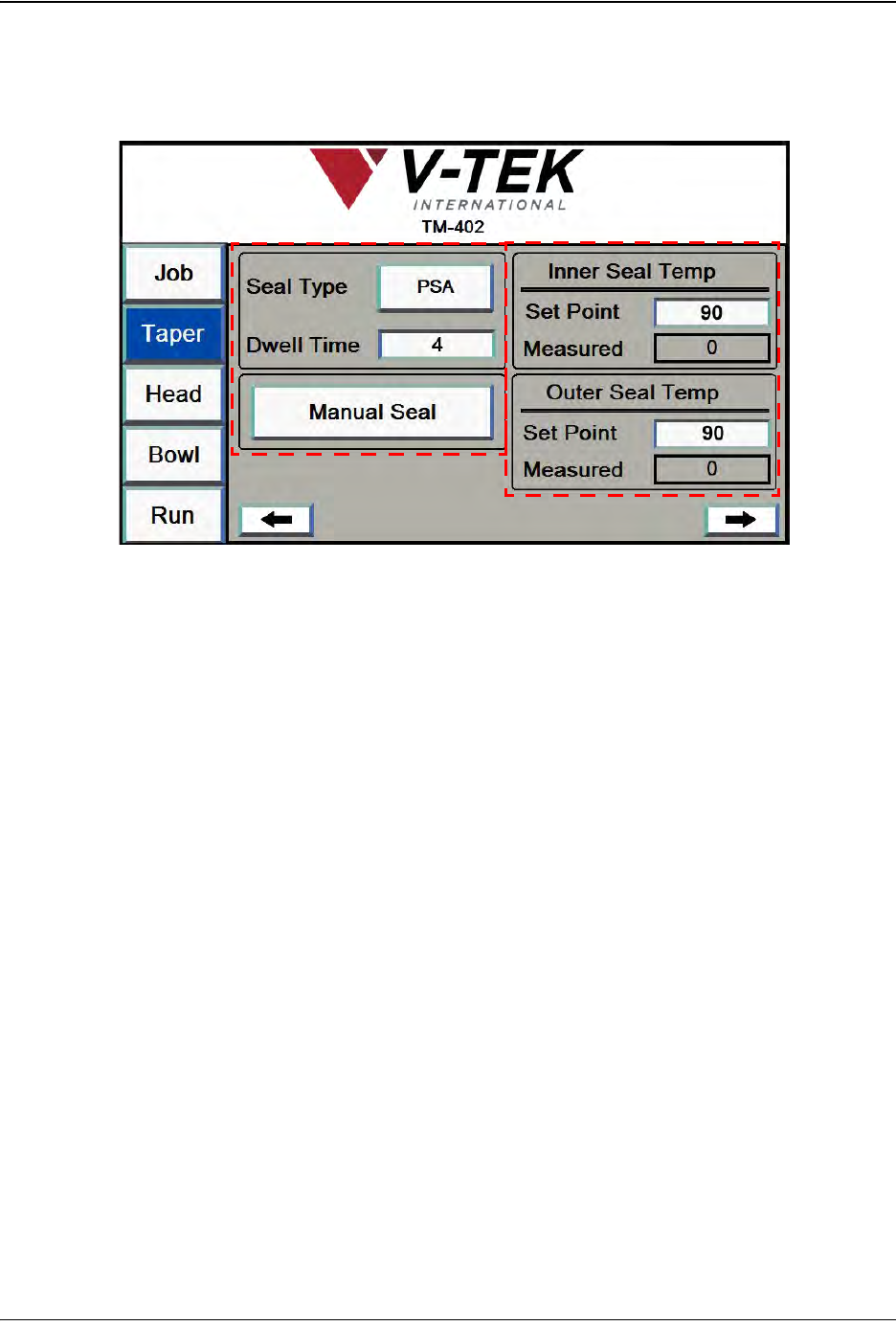
3. The third Taper Setup screen focuses on Sealer Settings. It will vary in appearance
depending on the type of sealer selected. In the example below, the selected Seal Type is
Heat.
A. The Seal Type button toggles between Heat seal and PSA seal.
The Dwell Time field is only active when heat seal is enabled. Dwell time refers to
the amount of time that the Heat Seal Shoes are in contact with the Cover Tape.
Enter the desired dwell time in milliseconds in this field.
The Manual Seal button activates the sealer to perform one seal.
B. The Set Point field allows the user to select the Heat Sealer set point, or target
temperature. Press the field to open the keypad, then enter the desired tempera-
ture in degrees Celsius.
The Measured field shows the current Heat Sealer temperature in degrees Cel-
sius.
Note: The TM-402 accommodates a wide range of carrier tapes and cover tapes. Set-
tings may vary from one tape product to another. The recommended starting point is 90°
C. The maximum recommended operating temperature is 160° C. The temperature for
each seal shoe should be increased or decreased as needed after running a peel force
test.
Taper Screen 3
A
B
3-20 TM-403 User’s Guide
Taper Tab D292105.6a.fm
4. Pressing the right Arrow button in the third Taper Setup screens opens the final Taper
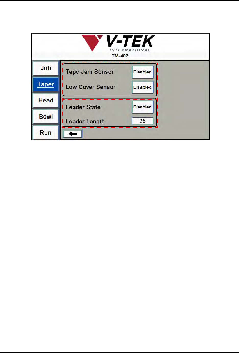
Setup screen. The fourth Taper Setup screen focuses on Leader and Sensor settings.
A. The Tape Jam Sensor Enabled/Disabled button turns the Tape Jam Sensor on
and off. The Tape Jam Sensor registers a tape jam whenever something pro-
trudes above the top of the carrier tape pocket. This might be caused by a mis-
placed part, a pocket that has been loaded with two parts or by a buckle in the
tape.
When the Tape Jam Sensor is activated, the job that is being run is paused and
an error message appears on the HMI screen. The recommended setting for the
Tape Jam Sensor is Enabled.
The Low Cover Sensor Enabled/ Disabled button turns the Low Cover Tape Sen-
sor on and off. The Low Cover Tape Sensor detects when the cover tape reel is
running low. When the Low Cover Tape Sensor is activated, an error message
appears on the HMI screen. The recommended setting for the Low Cover Tape
Sensor is Enabled.
Note: The Low Cover error message is only displayed once during a job.
B. When Leader State is enabled, the TM-402 will create a leader of the specified
length at the end of the job.
The Leader Length field is only active when Leader State is enabled. Enter the
desired leader length in millimeters in the field.
Note: The TM-402 will use these settings for the current job. To save Taper Settings for
future jobs, go to the Job Tab, select a job name and Save. If settings are not saved, all
data is lost when the TM-402 is powered off.
Taper Screen 4
A
B
D292105.6a.fm Head Tab
Chapter 3: Human Machine Interface 3-21
Head Tab
The three Head Setup Tab screens allow the user to set pick and place head positions, head
speed, and blow off time. There are also buttons that allow the user to manually pick, place and
rotate parts.
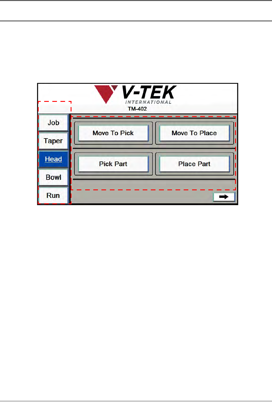
1. Head Screen 1 is used to position the head.
A. Press any tab in the Tab Menu to open that tab window.
B. The Move To Pick button moves the head to the preset Pick Positions.
The Move To Place button moves the pick head to the preset Place Position.
The Pick Part button moves the head from its current location and picks a part
from the programmed pick location. It then returns the nozzle to its Ready
(retracted) position.
The Place Part button moves the head from its current location and places a part
into the programmed place position.
A
B
Head Screen 1