编带机说明书-含图纸ttm402.pdf - 第187页
Chapter 8: Maintenance Content s Safe Maintenance S teps . . . . . . . . . . . . . . . . . . . . . . . . . . . . . . . . . . . . . . 8-2 Maintenance . . . . . . . . . . . . . . . . . . . . . . . . . . . . . . . . . . . .…
7-30 TM-403 User’s Guide
Adjusting PSA Seal Quality D292105.9b.fm
Adjusting PSA Seal Quality
If a Peel Force Test determines the PSA Sealer is not generating a satisfactory seal, try one of
the adjustments below to improve seal strength.
Check Sealer Settings
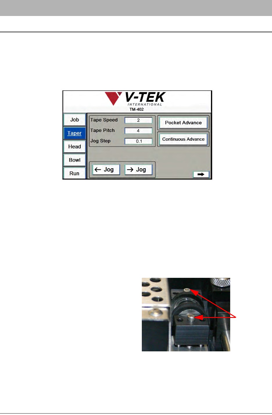
Open the HMI Taper Tab. Review the settings on the four Taper Tab screens to ensure Tape
Settings and Sealer Settings are appropriate for the current job.
Materials Used
For a PSA seal, seal strength is determined first by the nature of the materials used. It is nor-
mally recommended to use the same brand of cover and carrier tapes together as the manufac-
turers use the appropriate adhesive to match the material used to make the carrier tapes.
Seal Roller Pressure
The second factor in PSA seal strength is the pressure applied to the cover tape as it is sealed to
the carrier tape. The seal should appear as a solid stripe and it should not show any inconsisten-
cies. If it does, the alignment of the cover tape should be confirmed and then the pressure to the
seal rollers adjusted.
On the top of each sealer block, there are three
holes with a screw in the center hole. With carrier
and cover tape loaded, spin the Sealer Wheel.
While spinning the Sealer Wheel, turn the screw
clockwise until the wheel no longer spins freely,
then turn the screw another 1/8 turn. The wheel
should be firmly in contact with the tape.
Adjust the seal roller pressure until the PSA
adhesive is firmly adhered to the carrier tape.
Experience will allow the operator to judge the correct adjustment by feel. Repeat for the other
sealer wheel.
Note: Excessive roller pressure may cause carrier tape advance problems or elongation
of sprocket holes in the carrier tape.
PSA Seal
Adjustment
Screws
Pressure

Chapter 8: Maintenance
Contents
Safe Maintenance Steps . . . . . . . . . . . . . . . . . . . . . . . . . . . . . . . . . . . . . .8-2
Maintenance . . . . . . . . . . . . . . . . . . . . . . . . . . . . . . . . . . . . . . . . . . . . . . .8-3
Routine Maintenance Schedule. . . . . . . . . . . . . . . . . . . . . . . . . . . . . . . . . . . . 8-3
General Maintenance Instructions . . . . . . . . . . . . . . . . . . . . . . . . . . . . . . . . . . 8-4
Lubrication . . . . . . . . . . . . . . . . . . . . . . . . . . . . . . . . . . . . . . . . . . . . . . . . .8-4
Air Pressure Regulator . . . . . . . . . . . . . . . . . . . . . . . . . . . . . . . . . . . . . . .8-4
Pick Head Maintenance. . . . . . . . . . . . . . . . . . . . . . . . . . . . . . . . . . . . . . .8-5
Nozzle Tip . . . . . . . . . . . . . . . . . . . . . . . . . . . . . . . . . . . . . . . . . . . . . . . . . . . . 8-5
Vacuum Levels. . . . . . . . . . . . . . . . . . . . . . . . . . . . . . . . . . . . . . . . . . . . . . . . . 8-5
Replace the Vacuum Filter. . . . . . . . . . . . . . . . . . . . . . . . . . . . . . . . . . . . . . . . 8-5
Check Actuator Belt Tension . . . . . . . . . . . . . . . . . . . . . . . . . . . . . . . . . . . . . . 8-7
Taping Module Maintenance. . . . . . . . . . . . . . . . . . . . . . . . . . . . . . . . . . .8-8
Heat Sealer . . . . . . . . . . . . . . . . . . . . . . . . . . . . . . . . . . . . . . . . . . . . . . . . . . . 8-8
Loading Track. . . . . . . . . . . . . . . . . . . . . . . . . . . . . . . . . . . . . . . . . . . . . . . . . . 8-10
PSA Sealer. . . . . . . . . . . . . . . . . . . . . . . . . . . . . . . . . . . . . . . . . . . . . . . . . . . . 8-10
Cover Tape Guide . . . . . . . . . . . . . . . . . . . . . . . . . . . . . . . . . . . . . . . . . . . . . . 8-10
8-2 TM-401 User’s Guide
Safe Maintenance Steps D292105.10a.fm
Safe Maintenance Steps
Caution! It is dangerous to service or maintain the TM-402 while it is con-
nected to air and power supplies.
Before performing any maintenance tasks, ensure the machine is stationary and
disconnect the electrical and pneumatic power supplies placing the unplugged
cables in clear view. Follow your company’s Lock-out/Tag-out Procedures.
Follow the steps below when performing routine maintenance or cleaning the TM-402.
1. Turn the TM-402 OFF.
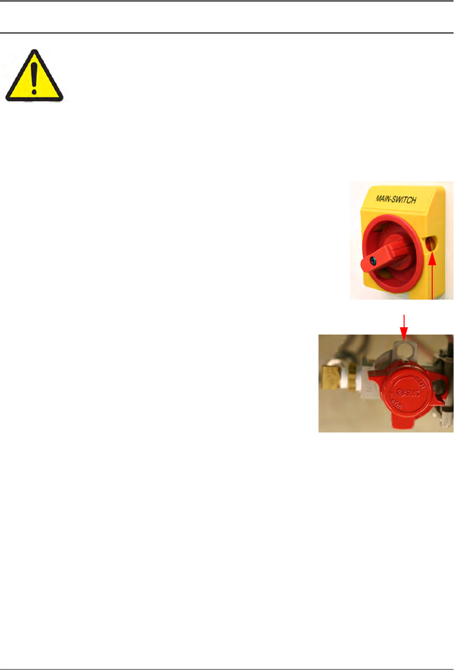
2. Ensure the Main Power Switch is rotated to the OFF position. The
Main Power Switch is Lock-out/Tag-out capable. Follow your com-
pany’s Lock-out/Tag-out procedure to ensure safe maintenance.
3. Ensure the Air Regulator is rotated to the OFF position.
The Air Regulator is Lock-out/Tag-out capable. Follow
your company’s Lock-out/Tag-out procedure to ensure
safe maintenance.
4. Disconnect the air supply and place the unplugged air
hose so it is clearly visible.
5. Disconnect the power supply and place the unplugged
power cord so it is clearly visible.
6. Remove all carrier and cover tape from the Taper.
7. Remove parts from the Bowl Feeder.
8. Perform cleaning/maintenance as needed.
9. Reload Bowl Feeder parts.
10. Reload Taper carrier tape and cover tape.
11. Reconnect the air supply.
12. Reconnect the power supply.
13. Turn the TM-402 back ON.
lockout/tagout hole