编带机说明书-含图纸ttm402.pdf - 第12页
Safety Features D292105.2a.fm viii Safety F eatures Main P o w er Switch The Main Power Switch is located on the right sid e of the machine. T urning the switch to the right turns power ON . T urning the switch back to t…
Operator Requirements D292105.2a.fm vii
Operator Requirements
The guidelines provided in the following pages are intended to educate the user about how to
operate the TM-402 safely. They contain important information on avoiding potential hazards to
the operator and to the equipment. Only personnel who have thoroughly reviewed and under-
stand the TM-402 User’s Guide and are aware of the possible hazards should operate or perform
maintenance on the TM-402.
Operators and maintenance personnel are advised not to wear loose fitting clothing or jewelry
when operating or maintaining the TM-402. Protective eye wear should be worn when loading,
operating or maintaining the TM-402.
Caution: Users should always wear protective eye wear when loading, operat-
ing or maintaining the TM-402.
Safe operation of the TM-402 does not require gloves of any type, however some component
manufacturers may recommend gloves be worn when handling parts. Consult the component
manufacturer for specific placement instructions. Ear protection is not necessary during normal
operation.
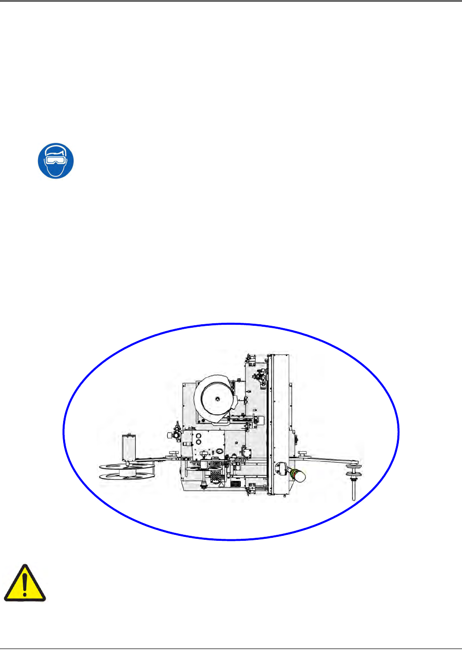
When running the TM-402, the operator should stand or sit in front of the touch screen to assure
easy access to all controls and the Power/Emergency Stop Button. This position allows the oper-
ator to view all parts of the TM-402 while it is in operation. When loading the TM-402 Bowl
Feeder or changing Taper reels, the operator may also need to access the side and back of the
machine
Caution!
The TM-402 should never be operated while under the influence of alcohol or drugs.
V-TEK® Incorporated takes no responsibility for the safety of TM-402 if it is used for
any purpose other than the intended purpose as specified in this User’s Guide.
Work Area
Safety Features D292105.2a.fm viii
Safety Features
Main Power Switch
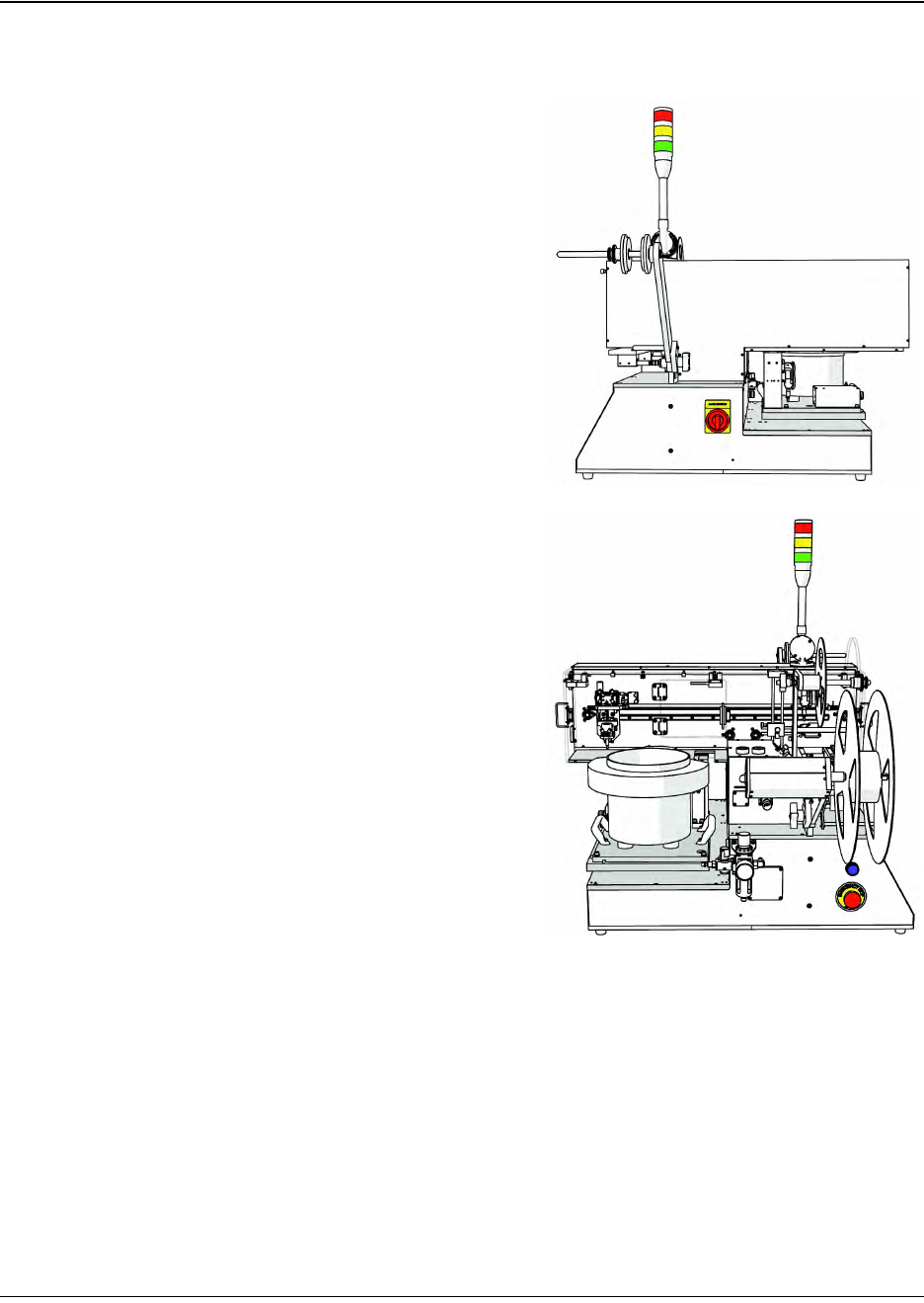
The Main Power Switch is located on the right side
of the machine. Turning the switch to the right
turns power ON. Turning the switch back to the left
turns the power OFF.
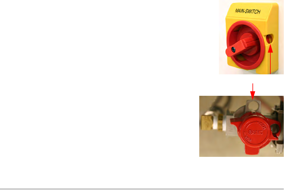
When the Main Switch is in the OFF position, it
exposes a lockout-tagout hole. The switch can be
locked by inserting a lock through the hole. The
switch on the right is pictured in the OFF position.
Emergency Stop Switch
There is one Emergency Stop Switch on the TM-
402. It is located on the left side of the machine
below the Take-up Arm. When an emergency stop
switch is triggered, all motion will be halted and the
machine will require a reset before operation can
continue.
The emergency stop control circuit removes elec-
trical power to all motors, moving parts, heat
sources, pneumatics, and energy storing devices.
This includes the stepper motor drive, stepper
motors, the servo motor drive, servo motors, drive
circuits, the main control board, the heat sealer
and all pneumatics. The only devices that remain
powered are the inspection module cameras, the
enclosure lights, the sensors, and the HMI.
Safety Features D292105.2a.fm ix
Reset Button
The TM-402’s blue Reset button is located on the left side of the machine above the Emergency
Stop Switch. When the machine is powered up, it is automatically placed into an emergency stop
state to prevent the motors from moving until the operator is ready to begin operating the
machine. The error state is cleared by pressing the Reset button on the front of the machine.
Open Doors Stop Operation
All automated motion stops and the machine is unable to enter Run Mode when an enclosure
door is opened. An error message will display at the bottom of the HMI Run screen alerting the
user that the TM-402 door(s) are open.
The enclosure doors may be left open during basic set-up procedures such as positioning the
pick head at place or pick locations. If the enclosure doors are left open during setup the TM-402
automatically reduces the speed of the pick head to a fraction of its normal operating speed to
prevent operator injury due to collision, etc.
Buzzer Alarm
The buzzer alarm will sound and halt the Run Mode process of the machine at any time a System
Alarm occurs. A description of the System Alarm and suggestions for resolving it will appear on
the HMI Main Screen.
Lockout/Tagout
The Main Switch can be turned ON and OFF by turning the
red knob back and forth. When the red knob is placed in the
OFF position, the lockout/tagout hole is exposed. The Main
Switch can then be locked out by placing a lock through the
hole.
The Air Regulator can be turned ON and OFF by turning
the top red cap back and forth. When the red cap is
placed in the OFF position, the lockout/tagout hole will be
exposed. The Air Regulator can then be locked out by
placing a lock through the hole.
Be sure to follow your company guidelines regarding
lockout/tagout procedures.
lockout/tagout hole