编带机说明书-含图纸ttm402.pdf - 第127页
D292105.16c.fm Configure Inspection Chapter 5: Setup 5- 29 Monitor Displa y: Menu ON 1. Title : Displays t he device name, the pr ogram number and the program name. 2. T ool name: Displays the tool number and the t ool n…
5-28 TM-403 User’s Guide
Configure Inspection D292105.16c.fm
Configure Keyence Monitor
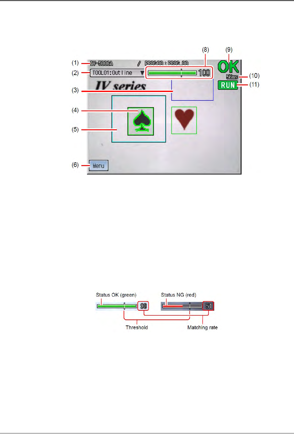
Monitor Display: Menu OFF
1. Title: Displays the device name, the program number and the program name.
2. Tool name: Displays the tool number and the tool name of the tool selected. The
selected tool can be switched.
3. Brightness correction range: When Brightness correction is set, the range will
be displayed with a blue frame.
4. Tool window: Displays the tool window which has been set.
5. Search Window: If the search window of the tool is set, the range will be
displayed with a light blue frame.
6. MENU/OFF button: Changes the screen from Menu ON to Menu OFF.
7. Status gauge: Displays the result (OK/NG) of the tool selected.
9. OK/NG display: Displays the total status result.
10. Processing time: Displays the time from receiving a trigger until the result is
output.
11. Image Type display: Displays the situation of the screen. Run mode or Test
mode.
Step 2:
Vision
Setup
CONFIGURE
MONITOR
D292105.16c.fm Configure Inspection
Chapter 5: Setup 5- 29
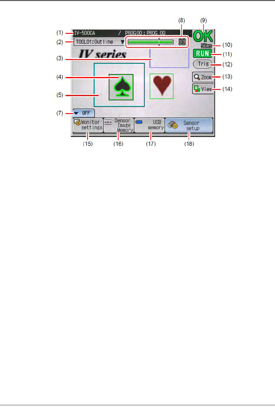
Monitor Display: Menu ON
1. Title: Displays the device name, the program number and the program name.
2. Tool name: Displays the tool number and the tool name of the tool selected. The
selected tool can be switched.
3. Brightness correction range: When Brightness correction is set, the range will
be displayed with a blue frame.
4. Tool window: Displays the tool window which has been set.
5. Search Window: If the search window of the tool is set, the range is displayed
with a light blue frame.
7. MENU/OFF button: Changes the screen from Menu ON to Menu OFF.
8. Status gauge: Displays the result (OK/NG) of the tool selected.
9. OK/NG display: Displays the total status result.
10. Processing time: Displays the time from receiving a trigger until the result is
output.
11. Image Type display: Displays the situation of the screen. Run mode or Test
mode.
12. Trig button: Displayed when the external trigger is set. When this button is
touched, a trigger signal is sent to the sensor.
13. Zoom button: Changes the display to full screen mode and allows image
enlargement.
14. View button: Displays the menu to select how to show the tools and the analyze
screen.
15. Monitor settings button: Displays the monitor screen.
Step 2:
Vision
Setup
CONFIGURE
MONITOR
5-30 TM-403 User’s Guide
Configure Inspection D292105.16c.fm
16. Sensor Image Memory button: Displays the Sensor Image Memory screen.
17. USB memory button: Displays the USB memory screen.
18. Sensor setup button: Stops running mode and displays the Sensor setup menu
screen.
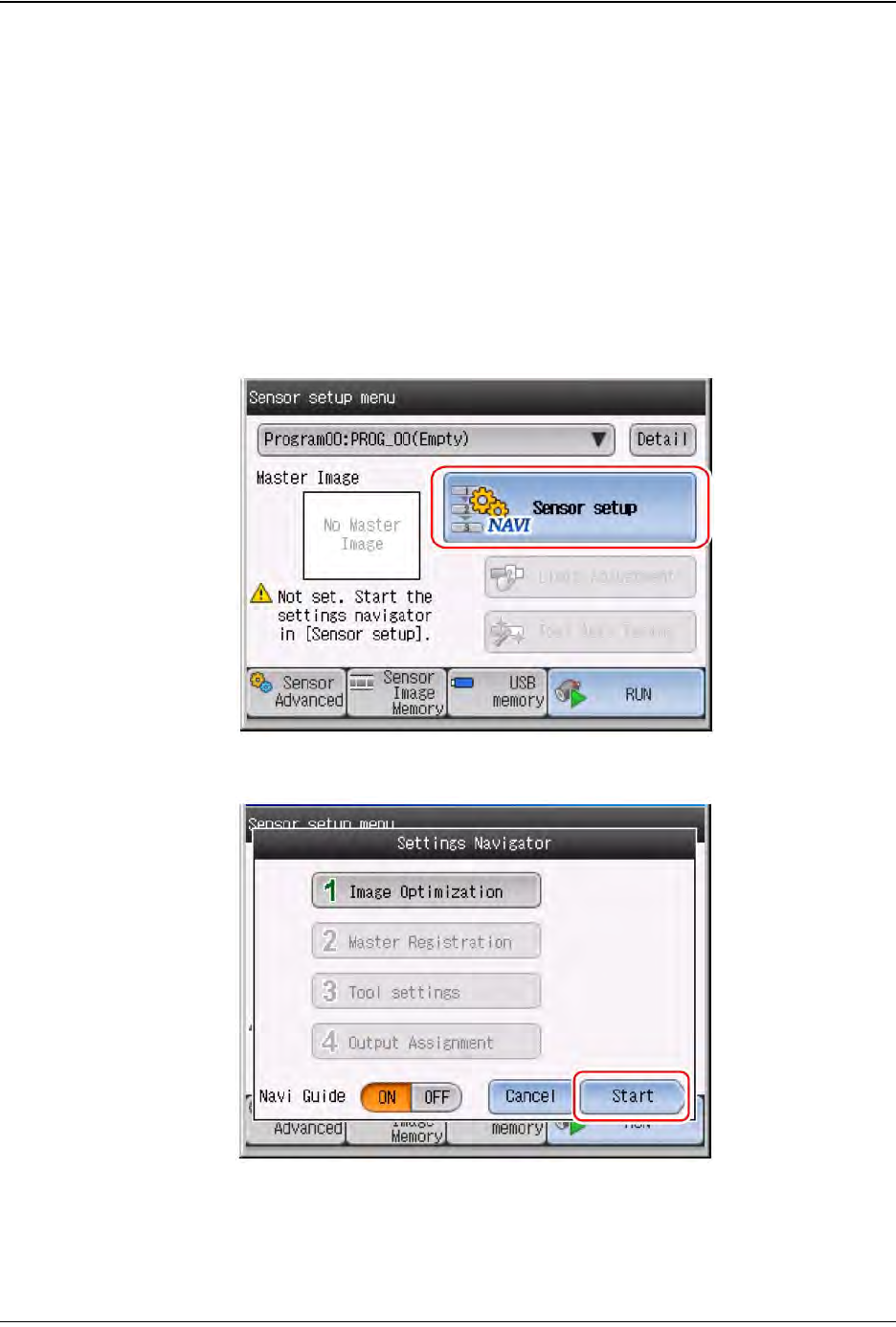
Program Job
Start Navigator
1. Touch the Sensor setup button.
2. Touch the Start button.
Step 2:
Vision
Setup
CONFIGURE
MONITOR