编带机说明书-含图纸ttm402.pdf - 第179页
D292105.9b.fm Adjusting Nozzle Vacuum Sensors Chapter 7: Troubleshooting 7-23 Adjusting Nozzle V acuum Sensors The TM-402’ s Nozzle V acuum Sensor is setup before the machine is shipped. It may occasion- ally require adj…

7-22 TM-403 User’s Guide
System Alarm Messages D292105.9b.fm
“The system is currently in a
halted state.”
Check the following:
- The Emergency Stop has been pressed. Resolve the
situation, then twist and release the. E-Stop button.
- The Reset Button has not been pressed. Press Reset.
- Once the condition is corrected, wait for system initial-
ization and home all motors.
“The HMI is in an error condi-
tion...”
- If an unacceptable value has been entered into a setup
field, change the value to one that fits that field’s parame-
ters.
- If this message persists, the Ethernet connection to the
PLC may have been lost. Contact V-TEK Service for sup-
port.
Error Condition Solution

D292105.9b.fm Adjusting Nozzle Vacuum Sensors
Chapter 7: Troubleshooting 7-23
Adjusting Nozzle Vacuum Sensors
The TM-402’s Nozzle Vacuum Sensor is setup before the machine is shipped. It may occasion-
ally require adjustment depending on vacuum sensitivity and the type of part that is being pro-
cessed.
If the TM-402 places “empty” pockets (i.e. places as though it held a part when it did not) or
returns a picking part error when it picked a part, the vacuum sensor’s threshold point probably
needs to be adjusted.
Vacuum Sensor Settings
1. Close the enclosure doors, then open the Head Setup Tab.
2. Press the Pick Part button to activate vacuum and pick a
part. Observe the vacuum sensor indicator which is located
on the Pick & Place Head above the nozzles. The numbers
should be lit in green with components on the nozzle and
red if components are not.
3. If the sensors require adjustment, Press the blue Set button
once. The sensor will alternately flash P_1 and the current
value.
4. Use the Up/Down Arrow Keys to adjust the sensor as
needed with components both on and off of the nozzles..
5. Press the blue Set button again to exit back to normal opera-
tion.
7-24 TM-403 User’s Guide
Tips on Part Placement D292105.9b.fm
Tips on Part Placement
If components are not dropped properly, there are four variables that can be adjusted to correct
the problem.
Note: Each part is different and may require a different combination of adjustments to
obtain proper place performance.
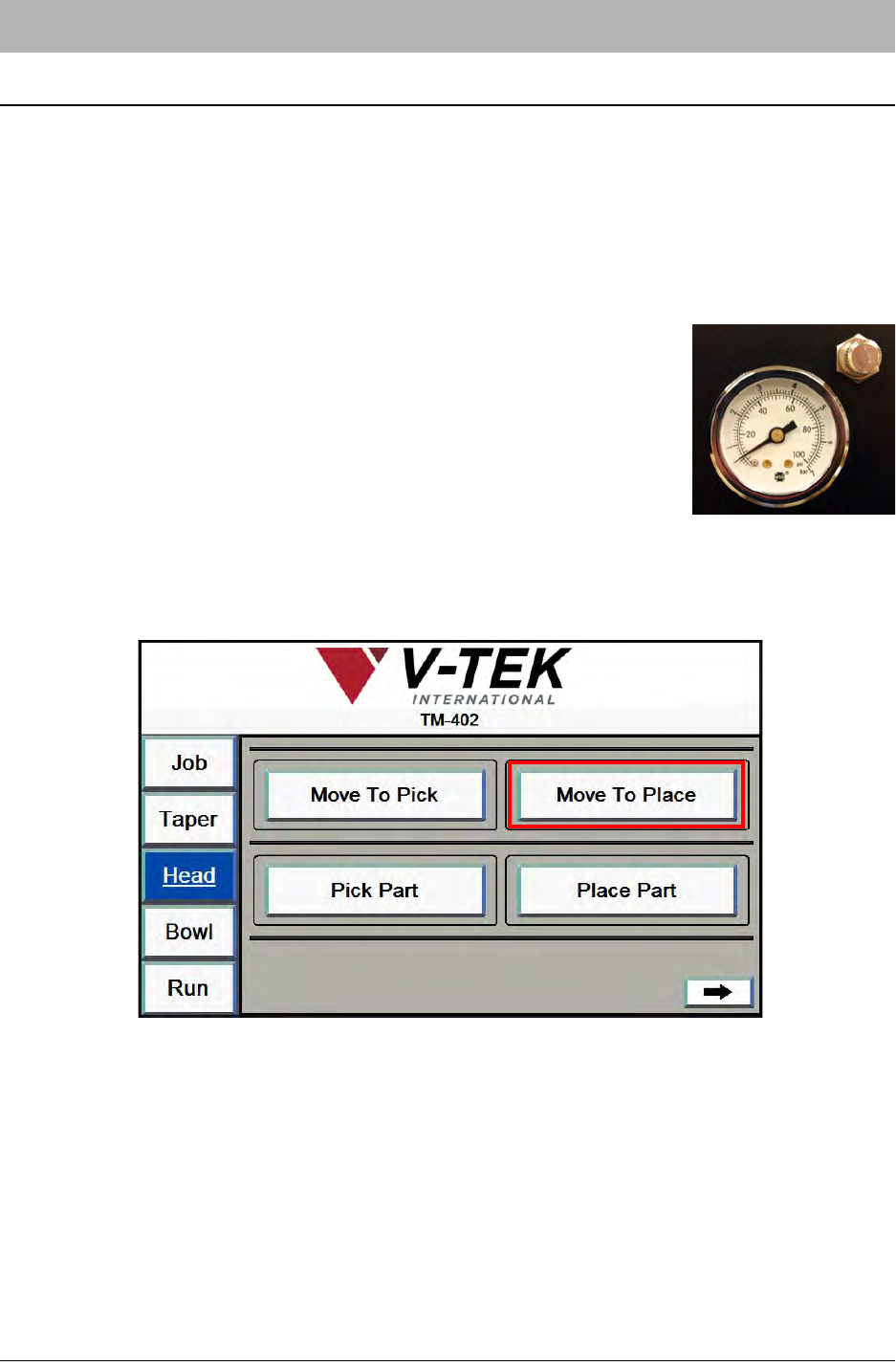
1. Adjust Blow-off Pressure. The Blow-off Pressure Gauge is
located on the front of the Pick Head enclosure. If components
are not dropping properly, pull the gauge out and rotate to adjust
pressure levels. When the desired pressure level is reached,
push the gauge back in.
Note: Every part is different and may require a different combi-
nation of adjustments to obtain proper place performance.
2. Adjust Place Position X. Open the HMI Head Tab. Press the Move To Place button.