编带机说明书-含图纸ttm402.pdf - 第200页
Appendix A: Sensors A-4 SMC ZSE30 Vacuum Sensor D291842.11.fm SMC ZSE30 V acuum Sensor The SMC ZSE30 V acuum Se nsor functions as a Pick & Place Head p art present sensor . It com- pares the vacuum pressure at the pi…

Keyence FS-N11CP & FSN12CP Sensor Amplifiers D291842.11.fm
A-3 Appendix A: Sensors
3. The CV Indicator will return to its normal display after 5 seconds have elapsed.
Locking the Keys
It is sometimes desirable to lock the keys of the sensor amplifiers so that the currents settings are
not inadvertently changed.
1. Hold down the Manual button and the Mode button simultaneously for at least three sec-
onds.
2. The CV indicator will display Loc to indicate that the lock is in place.
3. Repeat the same procedure to unlock the keys. The display will flash the message unL.
Two-point Calibration
1. With an obstructing object between the sensors (ideally, a full reel of cover tape), press
and release the SET button. The PV Indicator will be lit.
2. Remove the obstruction between the sensors and press SET again. The amplifier will
return to its normal operating mode. The number shown on the PV Indicator should
change.
3. If the sensor is in dark-ON mode, the operation indicator should be lit while there is an
obstruction between the sensors. If the sensor is in light-ON mode, the operation indica-
tor should be lit while there is no obstruction between the sensors.
Appendix A: Sensors A-4
SMC ZSE30 Vacuum Sensor D291842.11.fm
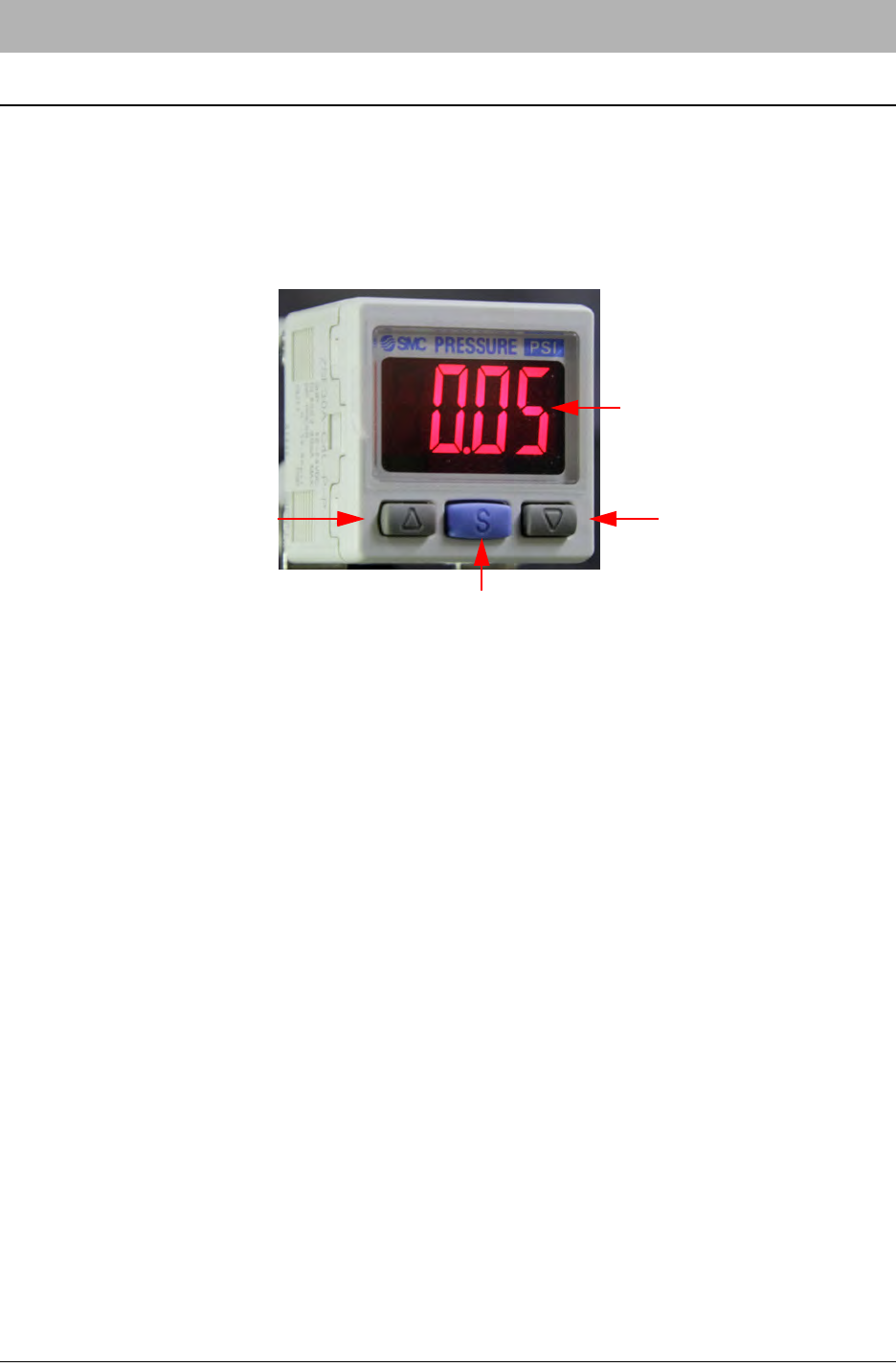
SMC ZSE30 Vacuum Sensor
The SMC ZSE30 Vacuum Sensor functions as a Pick & Place Head part present sensor. It com-
pares the vacuum pressure at the pick and place nozzle to a threshold point.
When the vacuum pressure drops beneath this level the sensor sends an OFF signal to the
machine (the LCD display will be green). When the vacuum rises above the threshold, the sensor
sends an ON signal to the machine (the LCD screen will be red).
Adjusting the Vacuum Sensor
If the machine places “empty” pockets (i.e., places as though it held a part when it did not) or
returns a picking part error when it picked a part, the vacuum sensor’s threshold point probably
needs to be adjusted.
To adjust the threshold point, follow these instructions:
1. With no part on the nozzle and the vacuum ON, note the reading on the vacuum sensor.
Example: -60.5.
2. Press the Set button. The sensor will alternately flash n_1 and the current setting. This is
the threshold point.
3. Using the Up Arrow and Down Arrow buttons, adjust the value of n_1 to about 5 less
than the pressure reading that was noted with no part on the nozzle. Example: -60.5 - 5 =
-65.5.
4. Press the Set button again. The sensor will now display the h (hysteresis) setting. This
should read 0.0.
5. Press the Set button again to exit back to Normal Operation mode. Run the machine and
observe if the vacuum sensor is functioning properly.
6. If the machine places empty pockets, set the threshold point closer to the pressure read-
ing when a part is on the nozzle. If the machine fails to detect a part on the nozzle when
Pressure Reading Display
Set Button
Up Arrow Button
Down Arrow Button

SMC ZSE30 Vacuum Sensor D291842.11.fm
A-5 Appendix A: Sensors
one is present, set the threshold closer to the pressure reading when no part is on the
nozzle. In this way, the optimum setting for each specific part can be reached.
Initial Factory Settings
If for some reason the sensor needs to be re-initialized to the default factory settings, follow the
steps below:
1. Press and hold the Set button for at least two seconds. The sensor will enter initialization
mode. The first setting to appear will be the Indication Unit setting. This should be set to
PA. Use the Up Arrows and Down Arrows to adjust this, if necessary.
2. Press the Set button to advance to the Display Color setting. This should be set to Sor
(Red/ON).
3. The next setting is the Operation mode setting. This should be set to HyS (hysteresis).
4. The next setting is the Output mode setting. This should be set to nC (normally closed). If
this setting is incorrect, the sensor will function backwards, such that the machine will not
detect a part when is on the nozzle and detect a part when no part is present.
5. The next setting is the Response Time setting. This should be set to 2.5.
6. The final setting is the Auto Preset setting. This should be set to mAn (manual).
7. Press the Set button to return to Normal Operation mode.