编带机说明书-含图纸ttm402.pdf - 第64页
3-22 TM-403 User’s Guide Head Tab D292105.6a.fm 2. Press the right Arrow button to open the second Head Setup screen (shown below). A. The Set Pick button saves the current position as the pick position. The Set Place bu…
D292105.6a.fm Head Tab
Chapter 3: Human Machine Interface 3-21
Head Tab
The three Head Setup Tab screens allow the user to set pick and place head positions, head
speed, and blow off time. There are also buttons that allow the user to manually pick, place and
rotate parts.
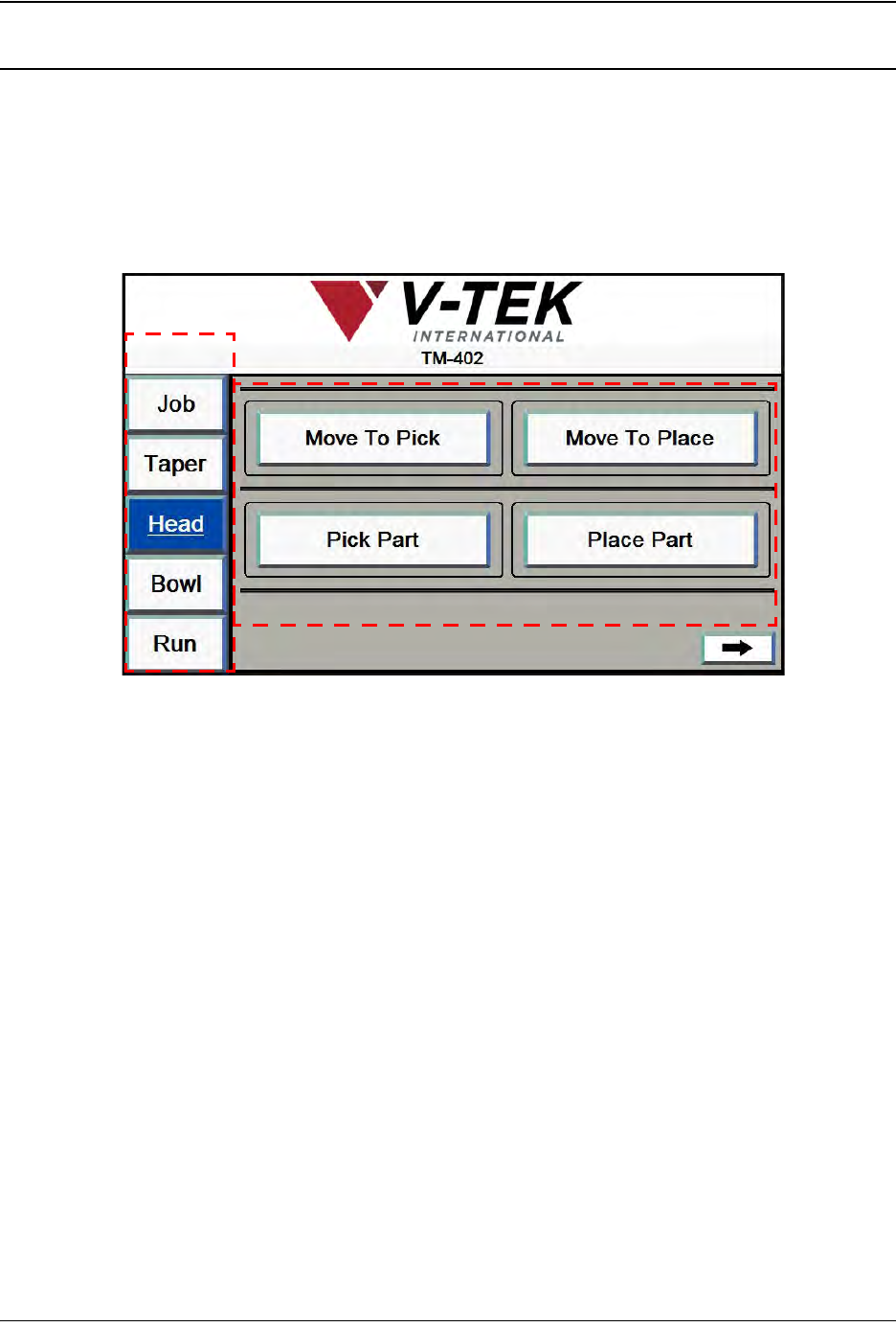
1. Head Screen 1 is used to position the head.
A. Press any tab in the Tab Menu to open that tab window.
B. The Move To Pick button moves the head to the preset Pick Positions.
The Move To Place button moves the pick head to the preset Place Position.
The Pick Part button moves the head from its current location and picks a part
from the programmed pick location. It then returns the nozzle to its Ready
(retracted) position.
The Place Part button moves the head from its current location and places a part
into the programmed place position.
A
B
Head Screen 1
3-22 TM-403 User’s Guide
Head Tab D292105.6a.fm
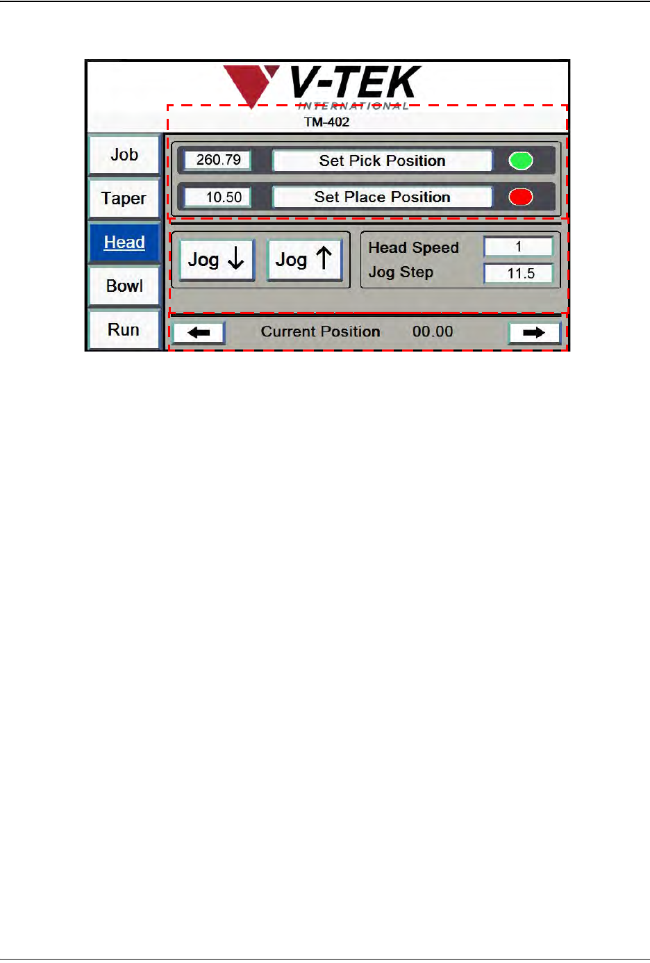
2. Press the right Arrow button to open the second Head Setup screen (shown below).
A. The Set Pick button saves the current position as the pick position.
The Set Place button saves the current position as the place position.
The user can either jog the head to the correct position or click inside the location
field to the left of the Set buttons and manually enter the correct position. Once
the correct position is entered, press the Set Pick/Place Position button to save
it.
If the position has been learned, the status color after the button will appear
green. If not learned, the status color will appear red. In the screen above, both
the Pick Position and the Place Position have not been learned.
B. The Jog buttons jog the head forward or backward along the X Axis (forward/
backward).
Head Speed is a percentage of the maximum velocity. It can be set between 1-10.
Jog Step is the distance in millimeters that the head will move when Jog is
pressed.
Note: The Jog Step field requires the value to be entered in the following format: XX.XX.
(i.e. 60.00).
C. The Current Position message show the location of the pick head in relation to
the Home position (when the head is closest to the front of the machine). For
example when the pick head is homed, the current position will be 0.00. This dis-
tance is measured in millimeters.
Head Screen 2
A
C
B
D292105.6a.fm Head Tab
Chapter 3: Human Machine Interface 3-23
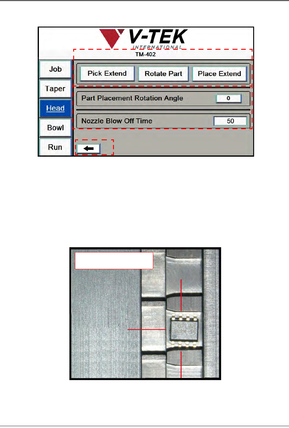
3. Press the right Arrow button to open the second Head Setup screen (shown below).
A. The Pick Extend/Pick Retract button actuates the pick solenoid to enable the
operator to set the pick height.
The Rotate Part button rotates the pick head to the preset rotation angle.
The Place Extend/Place Retract button actuates the place solenoid to enable the
operator to set the place height.
B. The Part Placement Rotation Angle is manually set during machine setup. The
options are 0, -90 and +90.
• If rotation is set at 0, the part will be placed in the same orientation as it was
picked.
Head Screen 3
A
C
B
-90
0
+90
Rotation Options