编带机说明书-含图纸ttm402.pdf - 第94页
4-22 TM-403 User’s Guide Configure HMI Settings D292105.7b.fm 12. Set Rot ation Angle a. Press the Placement Rot ation Angle field to toggle through the rot ation options. The options are 0, -90 and +90. Select the corre…
D292105.7b.fm Configure HMI Settings
Chapter 4: Setup 4- 21
keys move the Pick Head forward and backward. The Left/Right Arrow keys
move the tape left and right in the Taper Track.
b. When the Nozzle is centered over the tape pocket, press Set Place Position
to set the position.
c. Press the right Arrow Key to move to the next Job Wizard screen.
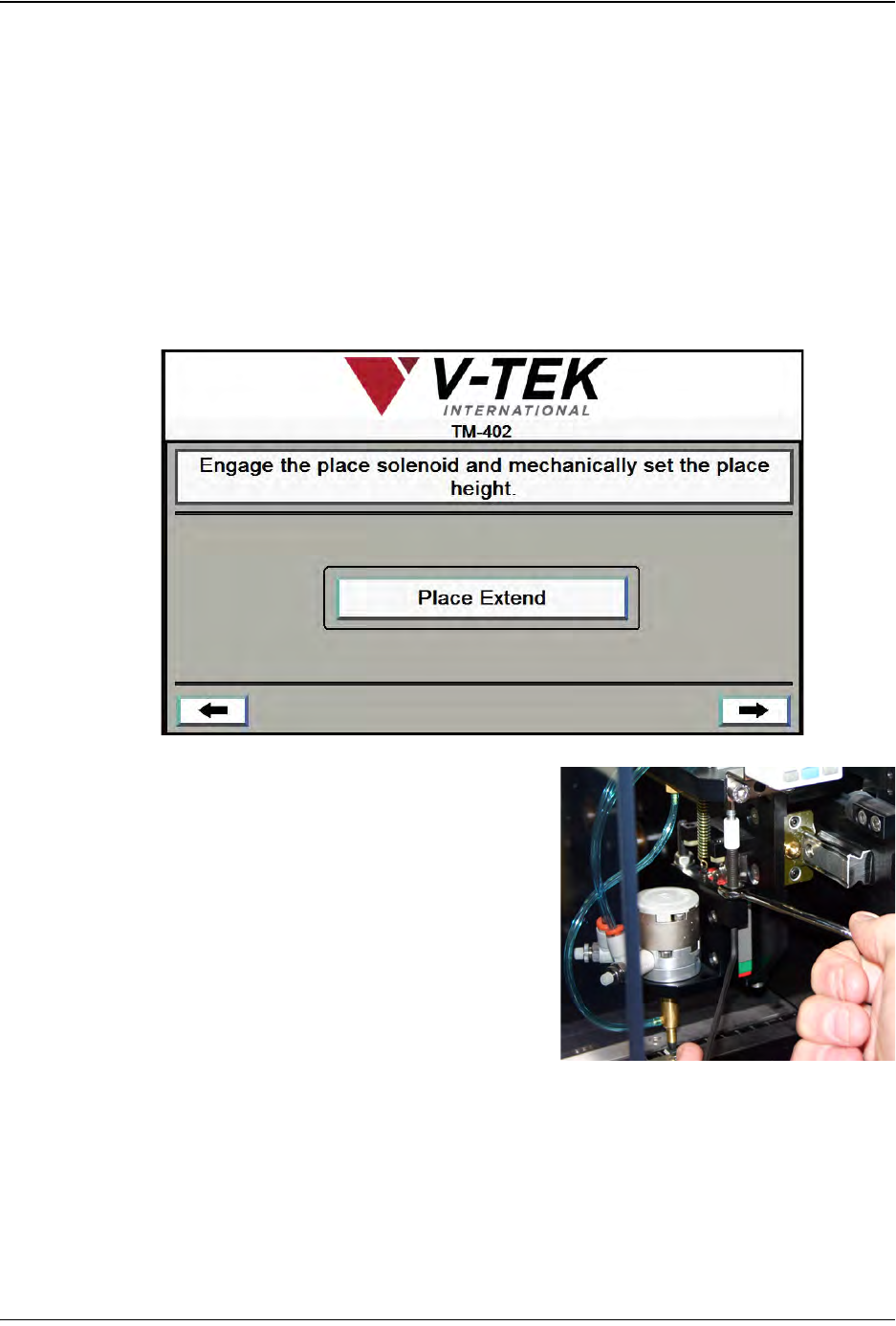
11. Set Place Nozzle Height The Pick Head’s Z Axis (up/down) position needs to be
set at the Place position.
a. To manually set the Place Actuator to
the correct nozzle height, press Place
Extend
b. Use a 2.5mm hex wrench to hold the
Actuator Adjustment Screw in place
from the bottom, while loosening the
Jam Nut on top of the Actuator
Adjustment Screw with an 8mm open
ended wrench. Lower the Nozzle until
the part is barely touching the top of
the pocket in the Place Location.
c. Tighten the Jam Nut.
d. Press Place Retract to retract the
Nozzle to a safe height.
e. Press the right Arrow Key to move to
the next Job Wizard screen.
Step 6:
Setup HMI
PICK
HEAD
4-22 TM-403 User’s Guide
Configure HMI Settings D292105.7b.fm
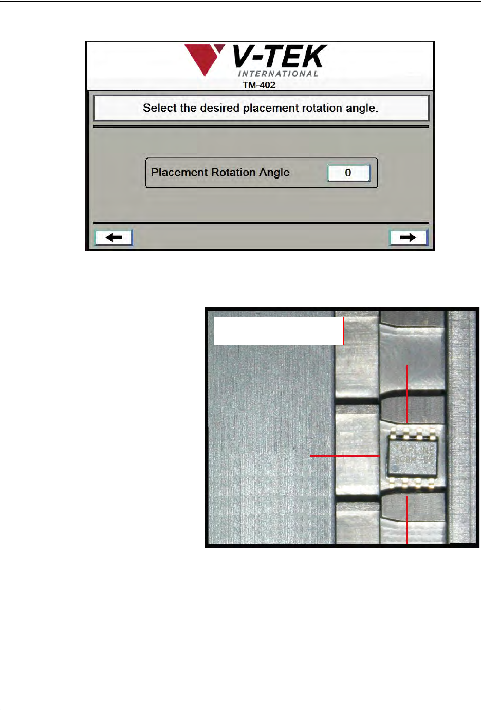
12. Set Rotation Angle
a. Press the Placement Rotation Angle field to toggle through the rotation
options. The options are 0, -90 and +90. Select the correct placement angle.
• If rotation is set at 0,
the part will be placed
in the same orientation
as it was picked.
• If rotation is set at -90,
the part will be rotated
90 degrees clockwise
prior to placement.
• If rotation is set at +90,
the part will be rotated
90 degrees counter-
clockwise prior to
placement.
b. Press the right Arrow Key to move to the next Job Wizard screen.
Step 6:
Setup HMI
PICK
HEAD
-90
0
+90
Rotation Options
D292105.7b.fm Configure HMI Settings
Chapter 4: Setup 4- 23
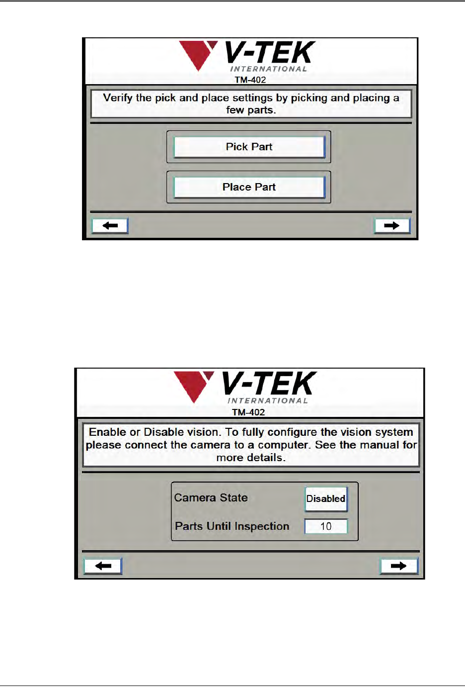
13. Verify Job Settings
Test the job settings, using the Pick Part and Place Part buttons to pick and
place parts. If adjustment are required, use the left Arrow key to return to the
desired step and adjust settings. Press the right Arrow Key to move to the next
Job Wizard screen.
Note: Manually placed parts will be counted in the current job.
14. Vision Settings
a. Set Camera State to Enabled or Disabled.
b. If camera is enabled, enter number of Parts Until Inspection (do not include
part at Pick point.). Press the right Arrow Key to move to the final Job Wizard
screen.
Step 6:
Setup HMI
VERIFY
Step 6:
Setup HMI
VISION