00194440-10_SM_X-Series_Customer_en.pdf - 第100页
Service Work Gantries 3.3.8 Replacing the Trailing Cable 100 Service Manua l SIPLACE X Series 3.3.8.5 3 . 3 . 8 . 5 R e p la c in g t h e H F T r a ilin g C a b le 0 3 0 3 9 7 0 9 - x x ] ] Replacing the HF Trailing Cabl…
Service Work
3.3.8 Replacing the Trailing Cable Gantries
Service Manual SIPLACE X Series 99
IGUS trailing cable for X4I/X series version 2 after machine serial number B-079
Depending on the arrangement of gantries, the following trailing cable types are available for SIPLACE
X series machines.
▪ Trailing cable for X series machines with one gantry:
X2 gantry 1/3, X3 gantry 3
– [03050655Sxx] Trailing cable digital 1P
▪ Trailing cable for X series and X4I machines in a placement area with two gantries and an uneven
number:
X3 gantry 1 and X4/X4I gantry 1/3
– [03050817-xx] Trailing cable SIPLACE X series 2P U
▪ Trailing cable for X series machines in a placement area with two gantries and an even number:
X3 gantry 4 and X4 gantry 2/4
– [03050934Sxx] Trailing cable digital 2P G
▪ Trailing cable for X4I machines in a placement area with two gantries and an even number (rotated
gantry):
X4I gantry 2/4
– For SIPLACE X4I only: [03051596-01] Trailing cable SIPLACE X4i 2P G
3.3.8.4
3.3.8.4 Handling the Hose Unlocking Tool [03047090-xx]
Handling the Hose Unlocking Tool [03047090-xx]
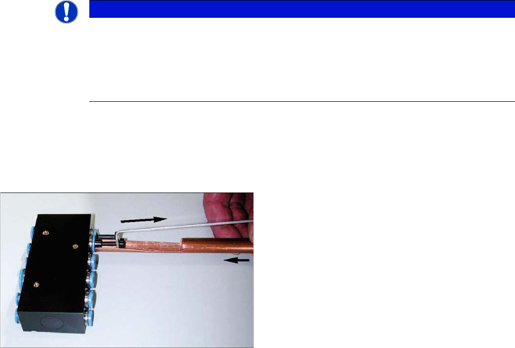
Due to the poor access to the pneumatic distributor, we recommend using an unlocking tool.
With the help of the hose unlocking tool [03047090-xx] you can open the unlocking ring (blue here) for
the compressed air connection. This enables you to remove both the hoses and the dummy plugs This
enables you to remove both the hoses and the dummy plugs (additional tool included in set).
NOTICE
Backwards compatibility
This version of the trailing cable is only backwards compatible if you also replace the hotlink
card [03054633-01] and the Vision board spread spectrum [03054634-01] and then only with
versions from B-079 up to now. Machines before B-079 can not be upgraded.
From version B-1071 onwards the hotlink card and the Vision board spread spectrum are no
longer necessary.
► Use the pipe-shaped tool (1) to open the unlocking
ring.
► Carefully pull the hose out of the compressed air con-
nection. The diagram shows the removal of a dum-
my plug (2), not a hose.
Service Work
Gantries 3.3.8 Replacing the Trailing Cable
100 Service Manual SIPLACE X Series
3.3.8.5
3.3.8.5 Replacing the HF Trailing Cable 03039709-xx]]
Replacing the HF Trailing Cable 03039709-xx]]
Parts
▪ Trailing cable, analog 1P [03039706-01]
▪ Trailing cable, analog 2P U [03038708-01]
▪ Trailing cable, analog 2P G [03039709-01]
▪ Hose pliers for cutting the pneumatic hose
▪ Pipe/hose cutters [00381443-01]
▪ Hose unlocking tool [03047090-xx]
▪ Locking varnish Loctite 241 [02101037-01]
Preparation
The trailing cable is supplied as a complete assembly. In accordance with your machine's configuration,
you will need to remove the relevant modules, covers and cover plates before you can dismantle the
trailing cable.
► Where necessary, remove the cover plates from the gantry trailing cable. Mark their exact position
to ensure correct replacement later.
► Remove the top central cover from the SIPLACE machine.
► Remove the upright EMC plates, so that you can reach the trailing cable.
See also
3.3.8.5.4 Conversion for SIPLACE HF up to A 219 [ ➙ 105]
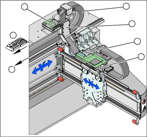
Overview
► The flat ribbon cables are run from the head
board (1), via the trailing cable console (2) and the
power track chain (3) to the gantry interface (7) and
the trailing cable interface gantry (4).
► The pneumatic hoses are fed from the pneumatic
distributor (6), via the trailing cable console (2) and
the power track chain (3) to the gantry distributor (5) .
5
5
6
7
1
4
3
2
Service Work
3.3.8 Replacing the Trailing Cable Gantries
Service Manual SIPLACE X Series 101
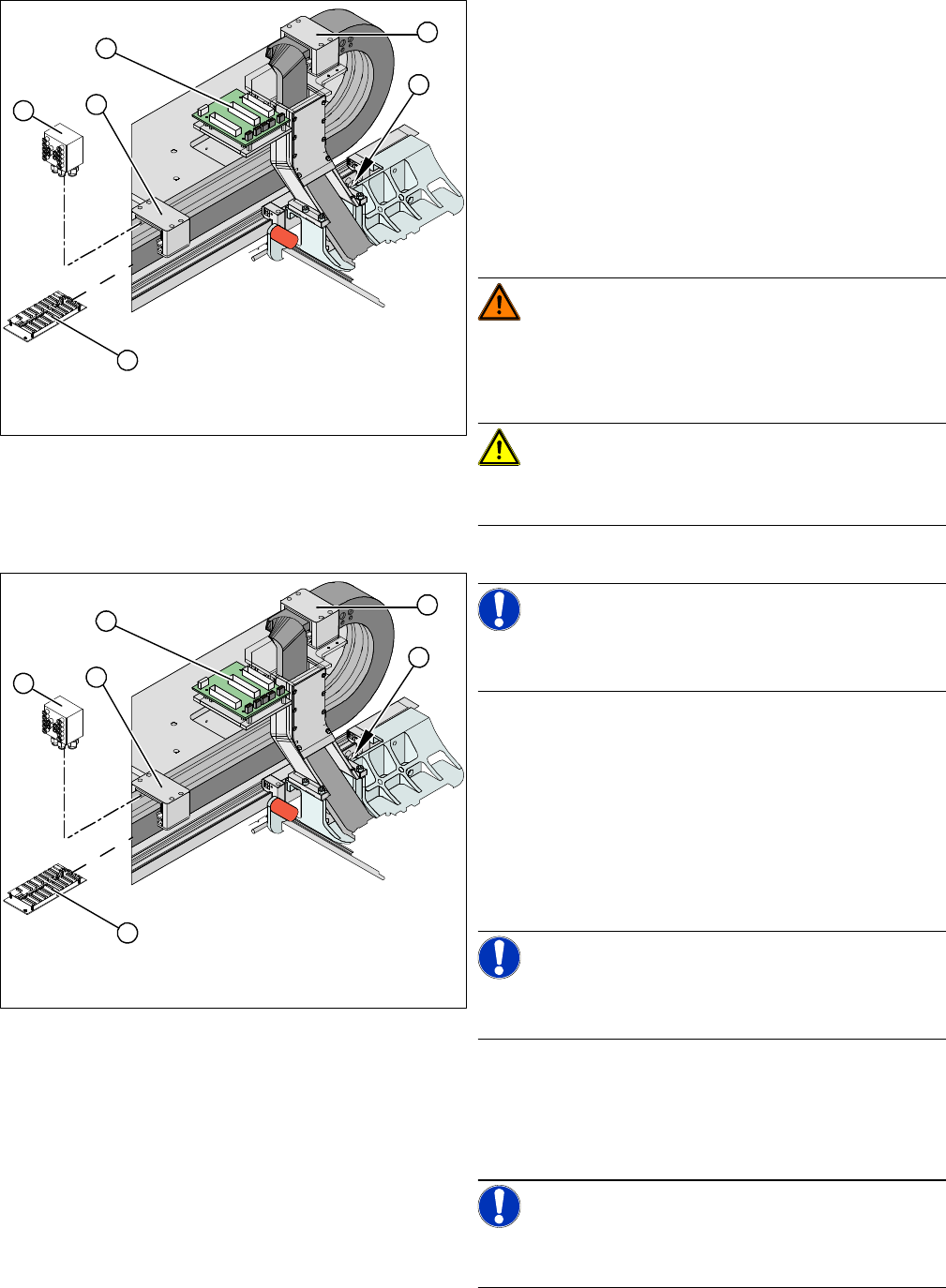
Removal
► Loosen the flat ribbon cable on the trailing cable inter-
face gantry (1). Take care not to lose the brackets for
the press-fit connections. They could fall out and be
lost.
► Remove cable ties where necessary.
► Remove the cover on the gantry distributor (5).
► Loosen the screws fastening the gantry distributor
(5).
► Disconnect the hoses from the pneumatic distributor
(2).
WARNING!
Risk of injury to hands
Use the hose unlocking tool to remove the hoses
[03047090-xx].
CAUTION!
Note the order in which the terminal connections are ar-
ranged. You will need this for subsequent reconnection.
NOTICE!
The gantry distributor must be reconnected to the new
trailing cable and then fitted back into the machine.
► Secure the end of the trailing cable (e.g. with cable
ties) in the machine to prevent it hanging loosely and
damaging other machine components.
► Remove the necessary cable ties at the gantry inter-
face (2) and disconnect the flat ribbon cable.
► Disconnect the motor, proximity switch, incremental
encoder and temperature sensor cables from the
gantry interface (2).
NOTICE!
The gantry interface board is installed on the cable clamp
of the new trailing cable.
► Disconnect the Y motor cooling tubes (4).
► Loosen the screws fastening the pressure plates (3)
to the power track chain. Note that the screws are se-
cured with locking varnish.
NOTICE!
Only loosen the fastening screws. The clamps for the flat
ribbon cable remain in place.
3
3
4
5
1
2
3
3
4
5
1
2