00194440-10_SM_X-Series_Customer_en.pdf - 第219页
Service Work 3.9.5 Replacing the Solenoid Valves [03 000630-xx] Cutter Service Manual SIPLACE X Series 219 Comparison of board press fit connections 3.9.5 3 . 9 . 5 R e p la c in g t h e S o le n o id V a lv e s [ 0 3 0 …
Service Work
Cutter 3.9.4 Replacing the Control Unit
218 Service Manual SIPLACE X Series
3.9.4.2
3.9.4.2 Replacing the Control Unit "CAN Nodes NC Tape Cutter X/HF" [03052927-xx]
Replacing the Control Unit "CAN Nodes NC Tape Cutter X/HF" [03052927-xx]
The control unit [03006411-xx] is replaced with a "CAN Nodes NC Tape Cutter X/HF" [03052927-xx].
General
The "CAN nodes NC tape cutter" module assumes the following tasks:
1. Cutter control (see Chapter Component Handling)
2. Nozzle changer control (row 1/2)
3. Valve control in the nozzle station
4. Sensor monitoring at the component and nozzle reject bin
The "CAN nodes NC tape cutter" is backwards compatible with the old tape cutter boards. This assem-
bly can therefore be used in X, HF and D series machines.
However, the nozzle station function (air blast valve C&P20A head) and the sensors for the reject con-
tainer CO/nozzles are not supported. The CAN nodes therefore need to be set accordingly via the jump-
ers. (See "6.4.2 Control Unit on Cutter (CAN Nodes)" [ ➙ 377].)
Removal/installation
NOTICE
Control via CAN nodes
Old nozzle changers, which were addressed via the one wire bus, are not able to communicate
via the CAN nodes. The new NC can be addressed via the one wire bus and CAN nodes.
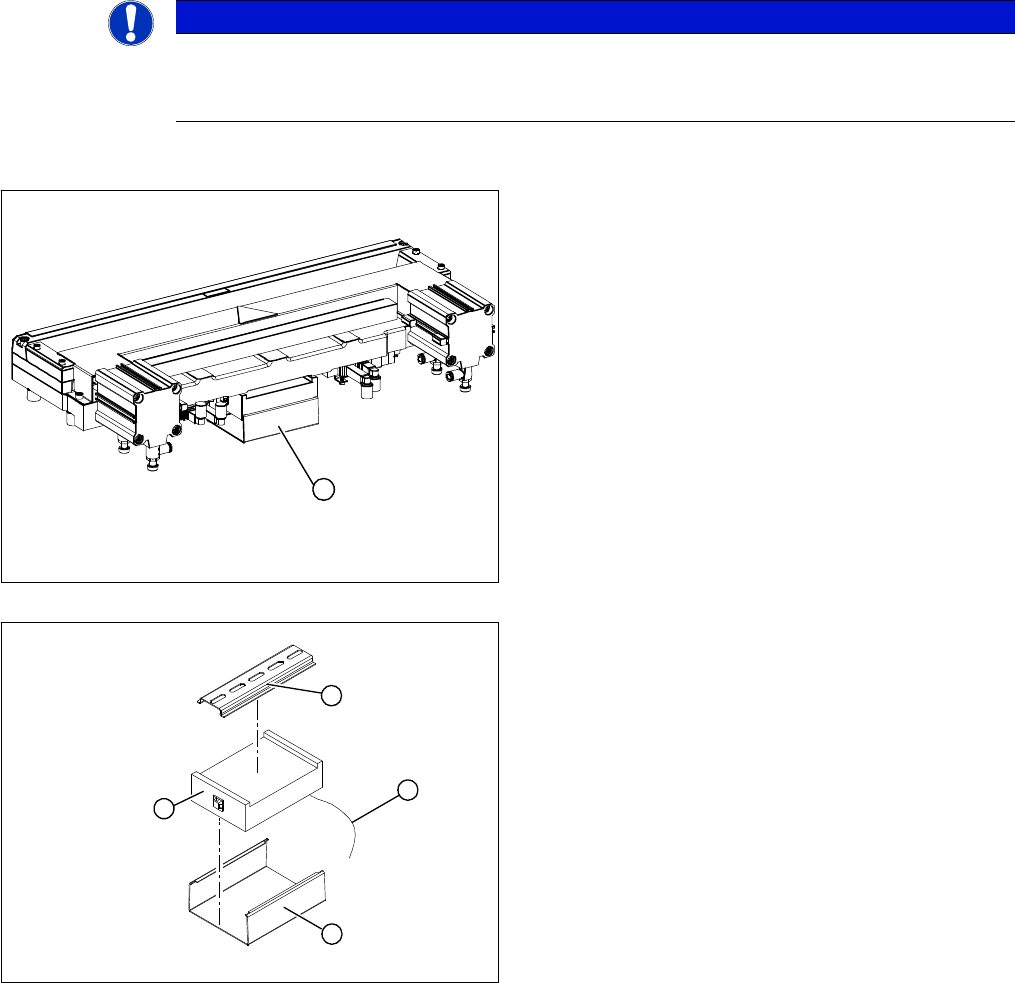
1. Control unit under the cover
► Remove the cover (1) from the control unit.
► Mark the allocation of all press-fit connections and
disconnect all press-fit connections (2) from the con-
trol unit.
► Remove the cable ties and the connection cable fix-
tures.
► Carefully pull the control unit (3) off of its mount (4).
► Carefully insert the new control unit onto the mount,
in the correct rotary position and location, until it locks
into place.
► Restore all plug-and socket connections in the cor-
rect allocation.
► Run the connection cables and fasten with cable ties
(strain relief).
► Replace the control unit cover.
1
1
4
3
2
Service Work
3.9.5 Replacing the Solenoid Valves [03000630-xx] Cutter
Service Manual SIPLACE X Series 219
Comparison of board press fit connections
3.9.5
3.9.5 Replacing the Solenoid Valves [03000630-xx]
Replacing the Solenoid Valves [03000630-xx]
Overview
Tape control unit [03006411-xx] CAN nodes NC tape cutter X/HF [03052927-xx]
Not connected X1 Energy supply with automatic CAN ID
Voltage supply for cutter +24 V and +5 V X2 X2 Energy supply, cutter +24 V/+5 V
Not connected X3 Sensors for reject container (nozzles, com-
ponents)
CAN bus connection X4 X4 CAN bus connection
Voltage supply to valve (left) X5 X5 Voltage supply to valve (left)
Voltage supply to valve (right) X6 X6 Voltage supply to valve (right)
Proximity switch for stroke cylinder in (left) X7 X7 Proximity switch for stroke cylinder move in
(left)
Proximity switch for stroke cylinder out
(left)
X8 X8 Proximity switch for stroke cylinder move out
(left)
Proximity switch for stroke cylinder in
(right)
X9 X9 Proximity switch for stroke cylinder move in
(right)
Proximity switch for stroke cylinder out
(right)
X10 X10 Proximity switch for stroke cylinder move out
(right)
X11 Test connector for cutter
X12 Air blast valve (additional air blast unit on the
nozzle station)
X13 Nozzle changer, row 1
X14 Nozzle changer, row 2
Jumper for location code of cutter: X12 S3 S3 DIP switch group S3
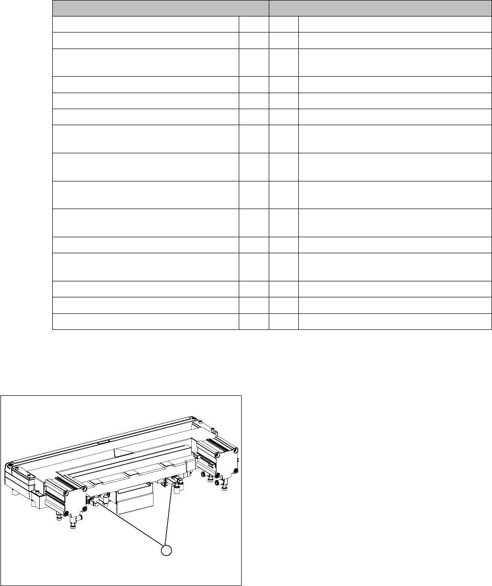
1. Position of the solenoid valves
1
Service Work
Cutter 3.9.6 Replacing the Proximity Switch (FSE) [00332894-xx]
220 Service Manual SIPLACE X Series
Removal/installation
3.9.6
3.9.6 Replacing the Proximity Switch (FSE) [00332894-xx]
Replacing the Proximity Switch (FSE) [00332894-xx]
Overview
Removal/installation
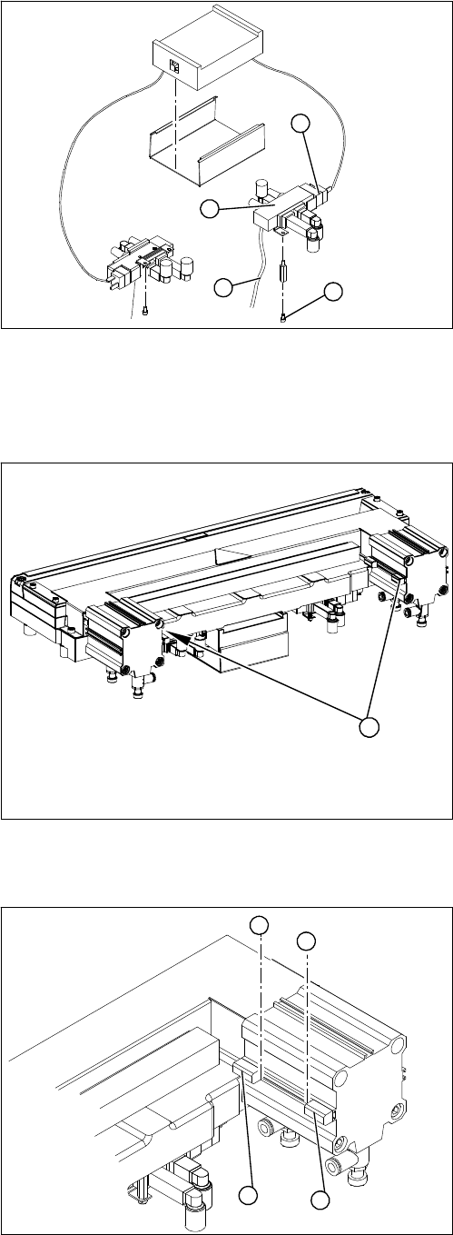
1. Solenoid valve assembly
► Loosen the compressed air connections (3) on the
solenoid valve.
► Unplug the press-fit connection (2) on the solenoid
valve connection cable.
► Loosen the screws (4) holding the solenoid valve in
place and remove the solenoid valve.
► Mount the new solenoid valve and make the press-fit
connection to the valve.
Attach cables ties, if necessary (strain relief).
1
4
3
2
1. Two proximity switches each on the short-stroke cyl-
inder
1
► Use a permanent marker to mark the exact installa-
tion position (3) of the proximity switch (1) or (2) on
the short-stroke cylinder.
► Loosen the screw fastening the proximity switch to
the short-stroke cylinder.
► Unthread the connection cable to the control unit.
► Install the proximity switch precisely in the position (3)
you marked with the permanent marker on the short-
stroke cylinder.
► Secure the fastening screws with locking varnish..
► Reconnect to the electricity supply.
► Check the switching points of the proximity switches.
1
2
3
3