00194440-10_SM_X-Series_Customer_en.pdf - 第325页
Settings 5.4.2 Setting the Fixed Conveyor Edge (SW60x) Conveyor Settings Service Manual SIPLACE X Series 325 ► Configure the new conveyor mode in SIPLACE Pro 5.4.2.4 5 . 4 . 2 . 4 R e - c o n v e r t in g S in g le C o n…
Settings
Conveyor Settings 5.4.2 Setting the Fixed Conveyor Edge (SW60x)
324 Service Manual SIPLACE X Series
Shaft fixtures (bearing flange)
See also
5.4.3.1.1 Setting the Fixed Conveyor Edge [ ➙ 326]
5.4.2.3
5.4.2.3 Connecting the Dual Conveyor Lifting Tables
Connecting the Dual Conveyor Lifting Tables
► Remove the lifting table plate on conveyor lane 2 in PA1 and on lane 1 in PA2.
► Loosen the lockscrew(s) (4) and use a screwdriver to push the hexagonal circlip over the shaft on
lifting table 1.
► Perform lifting table connection for all placement areas (arrangement rotated by 180°.)
NOTICE
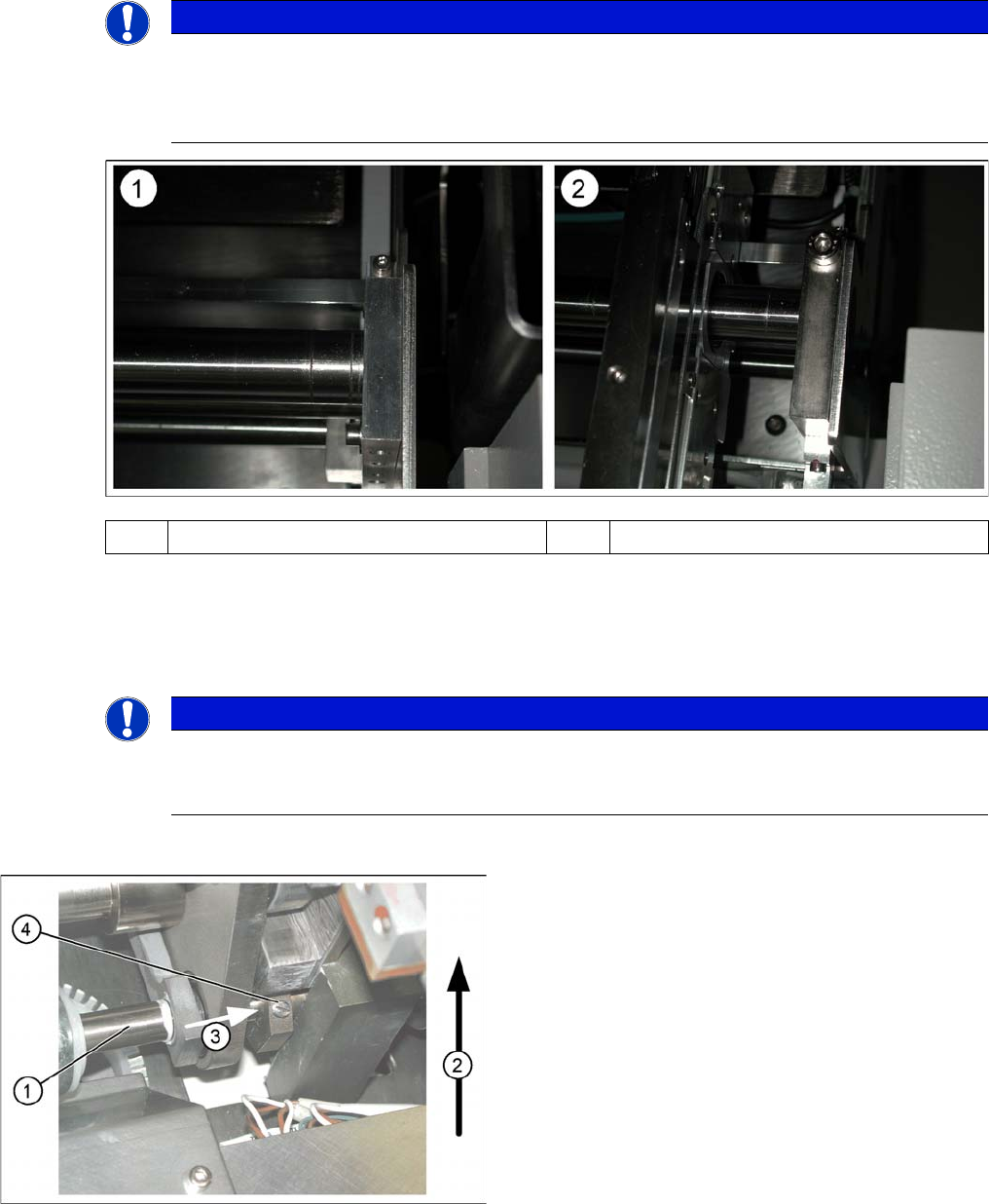
Various versions
Since July 2007, X machines with single conveyors use a new version of the shaft fixtures
(bearing flange) with a width of 15 mm, instead of 12 mm. The setting for standard single con-
veyors changes with this new version, to 40 mm.
(1) Bearing flange – first version 12 mm (2) Bearing flange – new version 15 mm
NOTICE
Why is “Alternative Components” a topic for our customers?
This option is a mechanical necessity when you use the dual conveyor as a single conveyor.
The two lifting tables move parallel when they are connected.
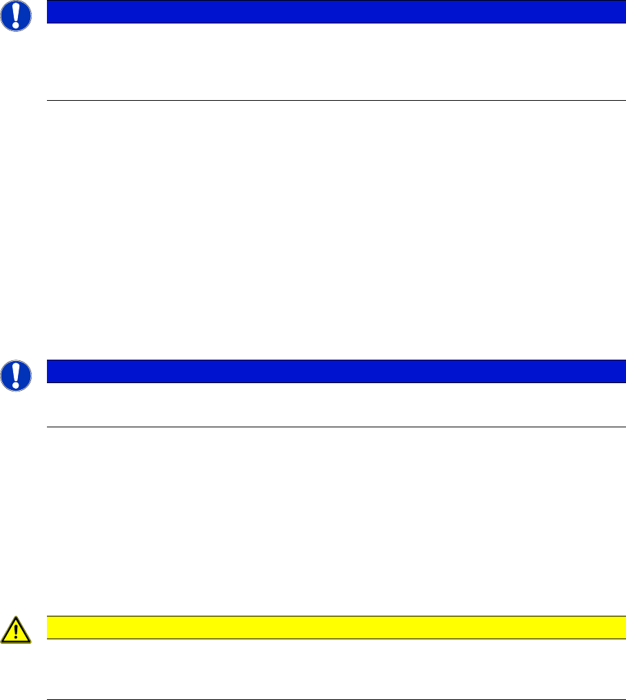
Connecting lifting tables (e.g. PA1 conveyor lane 2
▪ The drive shaft (1) is connected to the piston rod of
the pneumatic cylinder. This shaft is connected with
the shaft of the lifting table from conveyor lane 1. The
lifting table drive shaft also has an additional rod with
a hexagonal circlip. This rod is pushed over the shaft
of lifting table 1.
▪ Direction of transport (2).
▪ Direction (3) in which the hollow shaft from lifting ta-
ble 2 (1 in PA 2) is to be moved to lifting table 1 (2 in
PA 2).
▪ Lock screws (4).
Settings
5.4.2 Setting the Fixed Conveyor Edge (SW60x) Conveyor Settings
Service Manual SIPLACE X Series 325
► Configure the new conveyor mode in SIPLACE Pro
5.4.2.4
5.4.2.4 Re-converting Single Conveyor Mode
Re-converting Single Conveyor Mode
► In the SITEST conveyor menu Options and Configurations, select the menu Change Widening of
Conveyor to set the default conveyor mode.
► The moveable conveyor side of conveyor 1 (right side fixed (track 1 left side fix)) is moved to a small
conveyor width.
► The SITEST SW ask to disconnect the lifting tables - Do so-.
► The SITEST SW will now use the conveyor control SW to move the fixed side of conveyor 2 (right
side is fixed (lane 1 left side fixed)) back to its standard position. Check the dimensions near the ad-
justment units.
► Now adjust conveyor width of both tracks to desired values.
5.4.2.5
5.4.2.5 Moving the Fixed Conveyor Edge for ’Extra Wide Conveyor’
Moving the Fixed Conveyor Edge for ’Extra Wide Conveyor’
The standard positions of the fixed conveyor edge(s) are defined according to the dimensions of the X4,
X3 and X2 machines. Due to the additional width of HF machines, HF lines with single conveyors can
have up to 508 mm wide boards; dual conveyors up to 250 mm wide boards on each lane.
► Go to the SITEST conveyor menu Options and Configurations and select Extra wide, to set the con-
veyor mode "extra wide".
► The fixed conveyor edge of conveyor 2 (right side fixed (track 1 left side fix)) remains in its position.
► The ’fixed conveyor of track 1(right side fixed (track 2 left side fix)) is moved 34mm outside. This al-
low the wider boards. The moveable side of track 2 (track 1 left side fix) could be set now to more
than 216 mm wide boards.
NOTICE
SITEST
When converting the dual conveyor to a single conveyor (flexible dual conveyor, connect the
lifting tables when requested to do so by SITEST (we recommend doing this without com-
pressed air supply to the lifting table). This function is supported by SIPLACE Pro .
NOTICE
HF, X and D machines
This operating mode is possible for HF, X and D machines with single or dual conveyors.
CAUTION
Measuring and calibrating
After the conversion process, you need to measure/calibrate the board reference corner and
the conveyor edges and then save this information in the machine data.
Settings
Conveyor Settings 5.4.3 Setting the Fixed Conveyor Edge (from SW701)
326 Service Manual SIPLACE X Series
5.4.3
5.4.3 Setting the Fixed Conveyor Edge (from SW701)
Setting the Fixed Conveyor Edge (from SW701)
5.4.3.1
5.4.3.1 General Notes
General Notes
Setting the Fixed Conveyor Edge
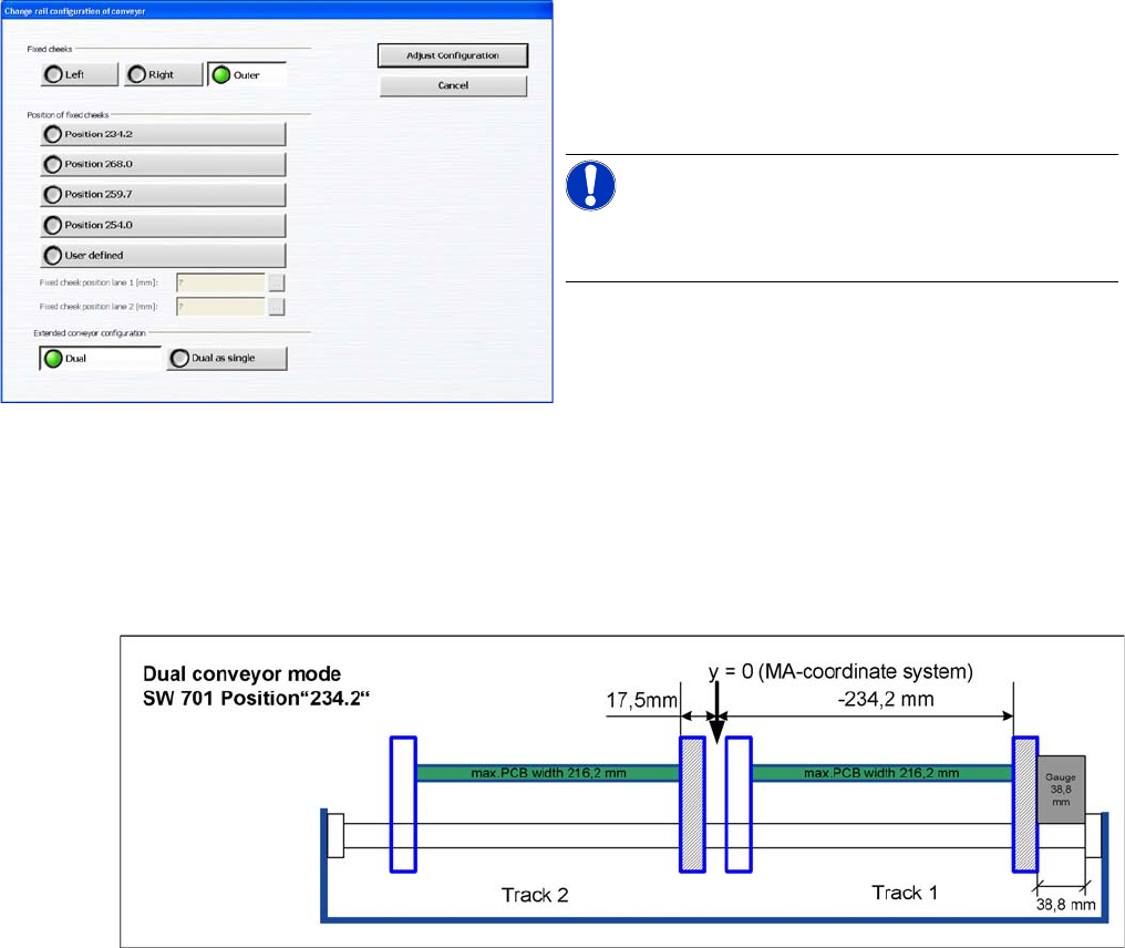
The fixed conveyor side is always set in the standard mode with right side fixed. You need to set a value
of 38.8 mm between the conveyor base and the fixed conveyor side, with the help of a gauge.
▪ [03054247-xx] Gauge for fixed conveyor edge DT/ET HS60/D4
▪ [03054248-xx] Gauge for conveyor edge distance DT HS-60/D4
Teach the fixed side with the software and store the value.
Setting the fixed conveyor side
When using dual conveyors in the X4I, the fixed conveyor
side can be set as required i.e. the left or right side, or the
outer edges of each conveyor for i-placement. The com-
patibility to the other machines can be set via predefined
values in the SW (see diagram).
NOTICE!
This menu is accessible from operator level Service (cus-
tomer)!