00194440-10_SM_X-Series_Customer_en.pdf - 第366页
Description of the Circuit Boards Gantry 6.2.3 Head Interface C500 366 Service Manua l SIPLACE X Series 6.2.3 6 . 2 . 3 H e a d I n t e r f a c e C 5 0 0 Head Interface C500 Head interface (C500) 1 X16 temperature sensor…
Description of the Circuit Boards
6.2.2 Head Adapter for C&P20A Gantry
Service Manual SIPLACE X Series 365
6.2.2
6.2.2 Head Adapter for C&P20A
Head Adapter for C&P20A
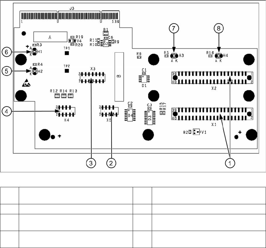
Head Adapter for C&P20A
1 X1, X2 connection to intermediate distribu-
tor
5 H2 LED (green) for DP motor 24 V display
2 X5 Z axis track signals 6 H1 LED (red) for 24 V display at C&P20
3 X3 Test connector: Serial Parallel Interface
(SPI) bus
7 H3 LED (green) for component sensor dis-
play
4 X4 star track signals 8 H4 LED (red) for hardware error display at
C&P20A
Description of the Circuit Boards
Gantry 6.2.3 Head Interface C500
366 Service Manual SIPLACE X Series
6.2.3
6.2.3 Head Interface C500
Head Interface C500
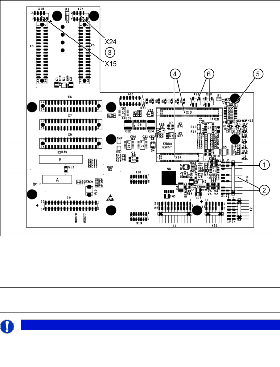
Head interface (C500)
1 X16 temperature sensor for X axis 4 X13 / X14 connector for 16 Bit processor
board (TQM module)
2 Proximity switches for X axis travel range
(not with A364)
5 DIP switch
3 X15 connector for incremental encoder X
axis (X24 connector digital track signals X
axis)
6 X20/X21 both connections can be used for
the temperature sensors.
NOTICE
X4I
In SIPLACE X4I machines, a mirrored version of the C500 head interface is used on gantries
2 and 4.
► Note the different item number!
Description of the Circuit Boards
6.2.3 Head Interface C500 Gantry
Service Manual SIPLACE X Series 367
6.2.3.1
6.2.3.1 LEDs on the Head Interface
LEDs on the Head Interface
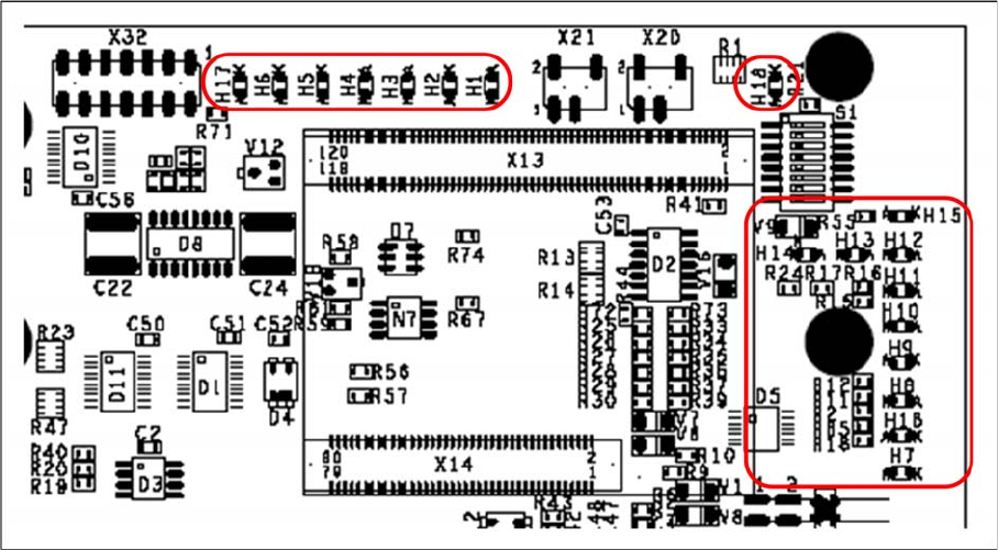
Head interface with status LEDs
LED H1-H6,H17,H18 (functional check)
▪ H17 SPI - Serial parallel interface (Test)
▪ H6 D-ON - digital ON 5V DC/DC converter (power supply head interface, generated from the 24V)
▪ H5 H-OK - Head adapter board connected
▪ H4 C-In - CAN Internal (status off)
▪ H3 MRST - Main Reset (always off)
▪ H2 F-UC – Failure - UC test
F-UC flashes red after machine is switched on:
- eSW was unable to execute one or more functions or to initialize a subsystem.
- flashes while the production power fail signal is active or 15V missing.
▪ H1 MP - Main Power fail, mean 5 V power supply being missing at the machine (e.g. CAN Bus)
▪ H18 1 Wire LED shows the high level on PIN 1 of 5V ON is green --> OK
LED H7- H15, H1B (LEDs for voltages)
▪ H14 Vcc - shows the output signal of the DC/DC converter (H6) +5 V
▪ H13 N15V – -15 V for TwinHead --> force measurement board (not for X4I)
▪ H15 P3.3V - Controller OK
▪ H12 P15V - Plus +15 Volt light barrier bottom C&P head
▪ H11 P24V - 24 V power supply (e.g.stepping motor)
▪ H10 AV ER - Failure 5 V
▪ H9 EN AN – 16 bit processor connected --> supply voltage OK
▪ H8 P5V - 5 V power supply track signals X axis --> red LED ON at error
▪ H1 B P5V – 5 V power supply for digital switching --> outside tolerance
▪ H7 X-Temp - Temperature monitoring X axis