00194440-10_SM_X-Series_Customer_en.pdf - 第65页
Service Work 3.1.6 Replacing the Computer Unit Assemblies Electrics and Co ntrol Service Manual SIPLACE X Series 65 3.1.6 3 . 1 . 6 R e p la c in g t h e C o m p u t e r U n it A s s e m b lie s Replacing the Comput er U…
Service Work
Electrics and Control 3.1.5 Replacing the Axis Unit Assemblies [00353054-xx]
64 Service Manual SIPLACE X Series
3.1.5.2
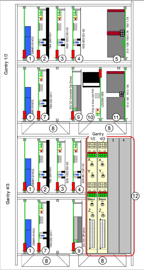
3.1.5.2 Overview of Axis Unit (with A364)
Overview of Axis Unit (with A364)
Axis unit with A364: configuration example C&P20 +
C&P20
From X-Series machine number B-337 and X4I onwards,
the axis card A364 [03041865-xx] has been fitted.
The anticrash board is no longer used as its function is in-
tegrated into the A364.
The plug-in cards can vary, according to the machine
configuration. This example shows an axis unit with two
C&P20 heads in placement area 2.
1. Brake board for each X axis and Y axis
2. Servo amplifier X axes
3. Star axis servo amplifier
4. Servo amplifier Z axis
5. Power supply +/- 15, +5 V
6. -
7. Servo amplifier Y axes
8. Fan unit
9. DC/DC converter, DP drives
10. Ballast circuit (only in axis unit PA2)
11. Power supply +/- 15V
12. Axis controller boards
Service Work
3.1.6 Replacing the Computer Unit Assemblies Electrics and Control
Service Manual SIPLACE X Series 65
3.1.6
3.1.6 Replacing the Computer Unit Assemblies
Replacing the Computer Unit Assemblies
3.1.6.1
3.1.6.1 Computer Unit [03002110-xx]
Computer Unit [03002110-xx]
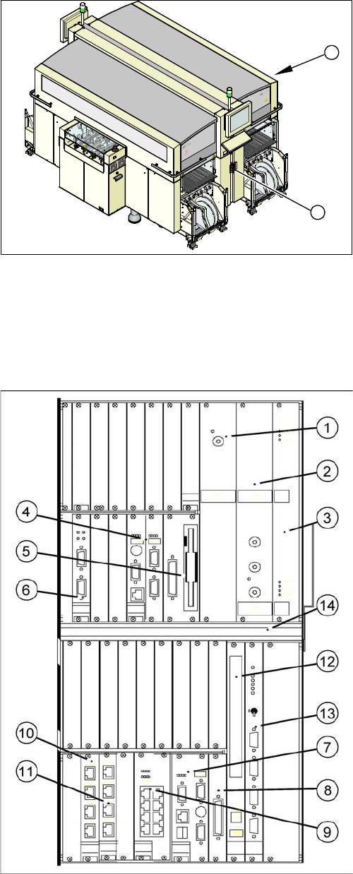
Overview
The backup battery 3.6 V is located at the back of the computer unit (on the outside of the rear panel
wiring board).
► End all placement operations on the machine.
► Switch the placement system off at the main switch
(1).
► Remove the cover on the computer unit (2).
⇨ If you wish to extract the computer unit, first re-
move the transportation locking screw.
1
2
Power supply / DC-DC converter
(1) Input +52 V / output +3.3 V, 20A
(2) Input +52 V / output +5.0 V, 60A
(3) Input +52 V / output +/- -12 V, 6A
Machine control (MC)
(4) CPU
(5) HD/FD drive
(6) CAN COM unit – connection above for PA1 / connec-
tion below for PA2
Control computer for station and Vision computer func-
tions (SR)
(7) CPU
(8) HD drive
(9) 2 x LAN interfaces for communication to the MC and
SIPLACE Pro computer
(10) 4 x hotlink interfaces for Vision functions /hotlink
card1: PA1
(11) 4 x hotlink interfaces for Vision functions /hotlink
card2: PA2
Other
(12) CD-ROM drive with USB connection
(13) Video multiplexer
(14) Fan unit
Service Work
Electrics and Control 3.1.6 Replacing the Computer Unit Assemblies
66 Service Manual SIPLACE X Series
3.1.6.2
3.1.6.2 Computer Unit with BoxPC
Computer Unit with BoxPC
See also
5.6.7 Installing the CAN Card Driver [ ➙ 358]
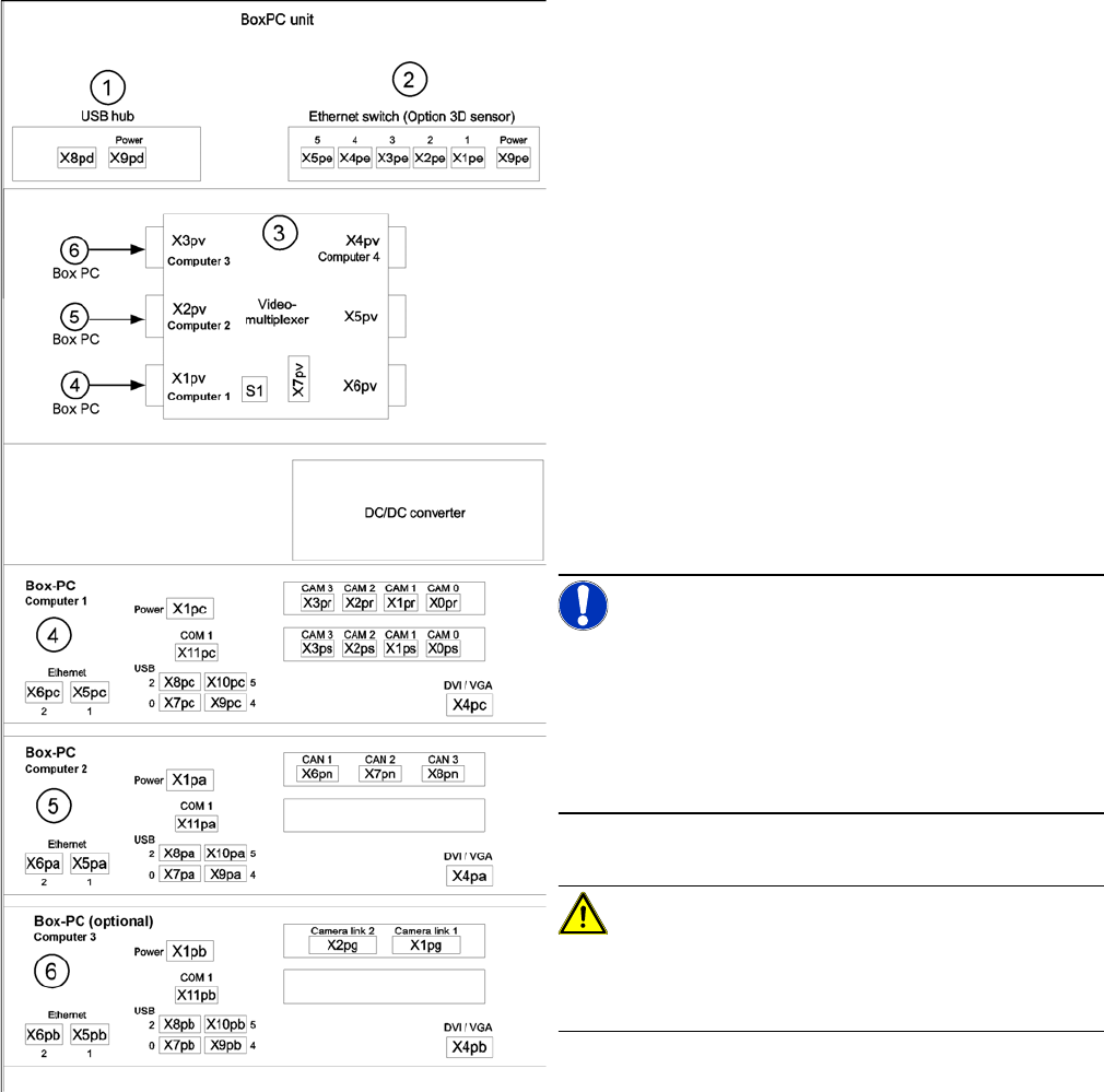
Computer unit with BoxPC [00351894-xx]
X series placement machines from machine number 600
onward and in X4I machines are equipped with box PCs
in the computer unit.
Depending on the machine type and the configuration up
to three box PCs are used.
Position of assemblies in the computer unit
1. 4 port USB hub 2.0
2. Ethernet switch (only for optional 3D sensor)
3. Video multiplexer
4. Computer 1:
Station computer (up to SW 60x)
Vision computer (from SW 70x)
5. Computer 2:
Machine controller (MC) (up to SW 60x)
Station computer / MC (from SW 70x)
6. Computer 3:
Additional box PC - only for optional 3D sensor (not
for X4I)
NOTICE!
An external DVD drive is supplied with the delivery pack-
age.
From SW702 (X series from SW703) onwards, X4I ma-
chines are supplied with higher performance BoxPCs
[03072079-xx]. This means that machine control and the
Vision function are handled by only one BoxPC.
CAUTION!
When fitting the box PC, make sure that it is not pushed
right to the back. This would cover the fan and impair the
cooling system.