00194440-10_SM_X-Series_Customer_en.pdf - 第30页
Overview of the Modules Electrical System 2.2.1 Axis Units 30 Service Manual SIPLACE X Series 2.2.1.7 2 . 2 . 1 . 7 P o s it io n s o f S e r v o C a r d s f o r S I P L A C E X S e r ie s a n d X 4 I Positions of Servo …
Overview of the Modules
2.2.1 Axis Units Electrical System
Service Manual SIPLACE X Series 29
2.2.1.5
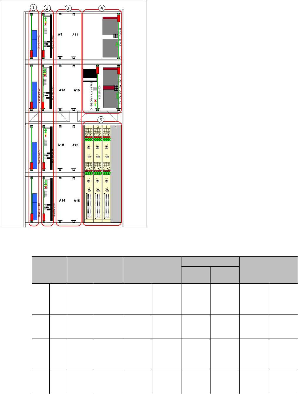
2.2.1.5 Overview of Axis Unit
Overview of Axis Unit
2.2.1.6
2.2.1.6 Servo Positions X Series
Servo Positions X Series
Servo positions
1. Brake boards X/Y
2. Servo amplifier X/Y
3. Head servo positions
4. Power packs, ballast circuit (new power packs with
downwards compatibility)
5. Axis controller boards
Head servo
positions
C&P6/12 C&P20 TwinHead CPP
Segment
2
Segment
1
A9 A11 SDS
120/
2.5S1-
03
SDS 60/
3Z1-02
SDS 120/
2.5S1-03
SDS 60/
2.5Z1-02
SDS 60/
1Z1-02
SDS 60/
1Z1-02
SDS 120/
2.5S1-03
SDS 120/
1.5Z2-01
A13 A15 -SDS 60/
1D1-02
- DC/DC
converter
DP drives
SDS 60/
0.5D1-03
SDS 60/
0.5D1-03
-DC/DC
converter
DP drives
A10 A12 SDS
120/
2.5S1-
03
SDS 60/
3Z1-02
SDS 120/
2.5S1-03
SDS 60/
2.5Z1-02
SDS 60/
1Z1-02
SDS 60/
1Z1-02
SDS 120/
2.5S1-03
SDS 120/
1.5Z2-01
A14 A16 -SDS 60/
1D1-02
- DC/DC
converter
DP drives
SDS 60/
0.5D1-03
SDS 60/
0.5D1-03
-DC/DC
converter
DP drives
Overview of the Modules
Electrical System 2.2.1 Axis Units
30 Service Manual SIPLACE X Series
2.2.1.7
2.2.1.7 Positions of Servo Cards for SIPLACE X Series and X4I
Positions of Servo Cards for SIPLACE X Series and X4I
Head servo cards for gantries 1 and 2
Head servo cards for gantries 3 and 4
2.2.1.8
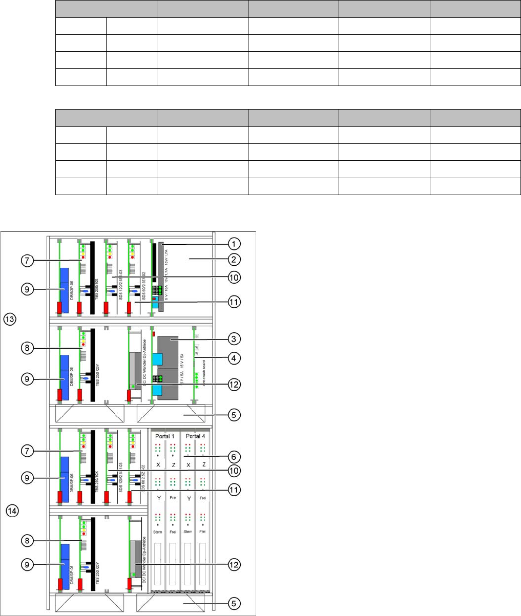
2.2.1.8 Example for Axis Unit A363 (X Series to Ma. No. B-335)
Example for Axis Unit A363 (X Series to Ma. No. B-335)
C&P6/12 C&P20 TwinHead CPP
A 9 Star axis Star axis Z2 axis Star axis
A 11 Z1 axis Z1 axis Z1 axis Z1 axis
A 13 Not connected Not connected DP2 axis Not connected
A 15 DP1 axis DC/DC converter DP1 axis DC/DC converter
C&P6/12 C&P20 TwinHead CPP
A 10 Star axis Star axis Z2 axis Star axis
A 12 Z1 axis Z1 axis Z1 axis Z1 axis
A 14 Not connected Not connected DP2 axis Not connected
A 16 DP1 axis DC/DC converter DP1 axis DC/DC converter
Axis unit with two C&P20 in placement area 1
1. Power supply +/- 15V, +5 V
2. Ballast circuit, only in axis unit PA2
3. Power supply +/- 15V
4. Anti-crash board
5. Fan unit (blows downwards)
6. Axis cards A363
7. Servo amplifier X axes
8. Servo amplifier Y axes
9. Brake board for each X axis and Y axis
10. Servo star axis (2x)
11. Servo Z axis (2x)
12. DC/DC converter DP drives (2x)
13. Placement area 1 gantry 1/2 (top half)
14. Placement area 1 gantry 3/4 (bottom half)

Overview of the Modules
2.2.1 Axis Units Electrical System
Service Manual SIPLACE X Series 31
2.2.1.9
2.2.1.9 Example for Axis Unit A364
Example for Axis Unit A364
Axis unit with two C&P20 in placement area 1
1. Power supply +/- 15V, +5 V
2. Ballast circuit, only in axis unit PA2
3. Power supply +/- 15V
4. Fan unit (blows downwards)
5. Axis card A364 for gantry 1/2
6. Axis card A364 for gantry 4/3
7. Servo amplifier X axes
8. Servo amplifier Y axes
9. Brake board for each X axis and Y axis
10. Servo star axis (2x)
11. Servo Z axis (2x)
12. DC/DC converter DP drives (2x)
13. Placement area 1 gantry 1 (top half)
14. Placement area 1 gantry 4 (bottom half)