00194440-10_SM_X-Series_Customer_en.pdf - 第244页
Service Work Docking Station for X-Series Component Trolley 3.12.10 Replacing the Control Valve [03003489-xx] 244 Service Manua l SIPLACE X Series 3.12.10 3 . 1 2 . 1 0 R e p la c in g t h e C o n t r o l V a lv e [ 0 3 …
Service Work
3.12.9 Replacing the Unlocking Pushbutton [00334095-XX] Docking Station for X-Series Component Trolley
Service Manual SIPLACE X Series 243
3.12.9
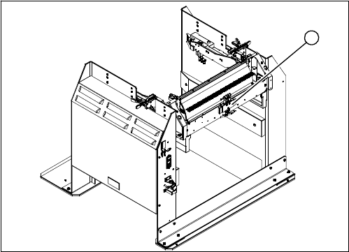
3.12.9 Replacing the Unlocking Pushbutton [00334095-XX]
Replacing the Unlocking Pushbutton [00334095-XX]
Parts, equipment and tools
▪ Unlocking pushbutton [00334095-xx]
Overview
Removal/installation
► Loosen the four screws (5) fastening the cover (3). The cover is clamped in place with the help of
the bar (4).
► Pull the cover (1) out of the docking station.
► Take care not to damage the earth connection.
► Loosen the screw fastening the terminal block (6) of the pushbutton.
► Turn the terminal block and extract it from its fixtures.
► Label the connection leads and disconnect these from the terminal block.
► Connect the connection cables to the new pushbutton.
► Fit the new pushbutton.
► Refit the cover.
► Connect the power pack connection cable and press the ON/OFF button to switch on.
► Check the function of the pushbutton, by trying out the unlocking procedure.
1. Unlocking pushbutton
1
1. ON / OFF switch
2. Power supply plug
3. Cover
4. Bar for clamping the cover
5. Four screws fastening the cover
6. Terminal block for pushbutton
DANGER!
Switch off the voltage supply
Press the ON/OFF button (1) to switch off, and then un-
plug the power supply (2).
4
6
5
1
3
2
Service Work
Docking Station for X-Series Component Trolley 3.12.10 Replacing the Control Valve [03003489-xx]
244 Service Manual SIPLACE X Series
3.12.10
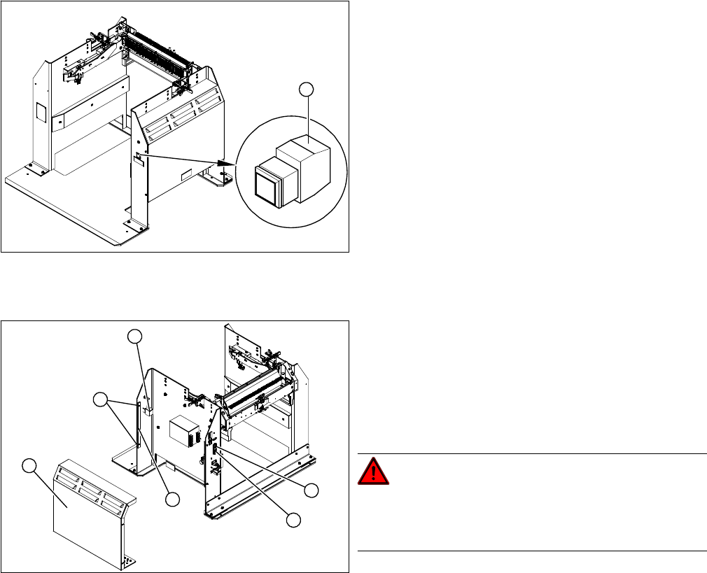
3.12.10 Replacing the Control Valve [03003489-xx]
Replacing the Control Valve [03003489-xx]
Parts, Equipment and Tools
▪ Control valve [03003489-xx]
Removal/Installation
► Unplug the electricity and compressed air cables
from the control valve (1).
► Loosen the fastening screws and remove the control
valve.
► Install the new control valve.
► Reconnect to the electrical and compressed air sys-
tems.
1
Measuring Equipment and Tools
SIPLACE Axis Tester (SAT) [03002801-01]
Service Manual SIPLACE X Series 245
4
4 Measuring Equipment and Tools
Measuring Equipment and Tools
4.1
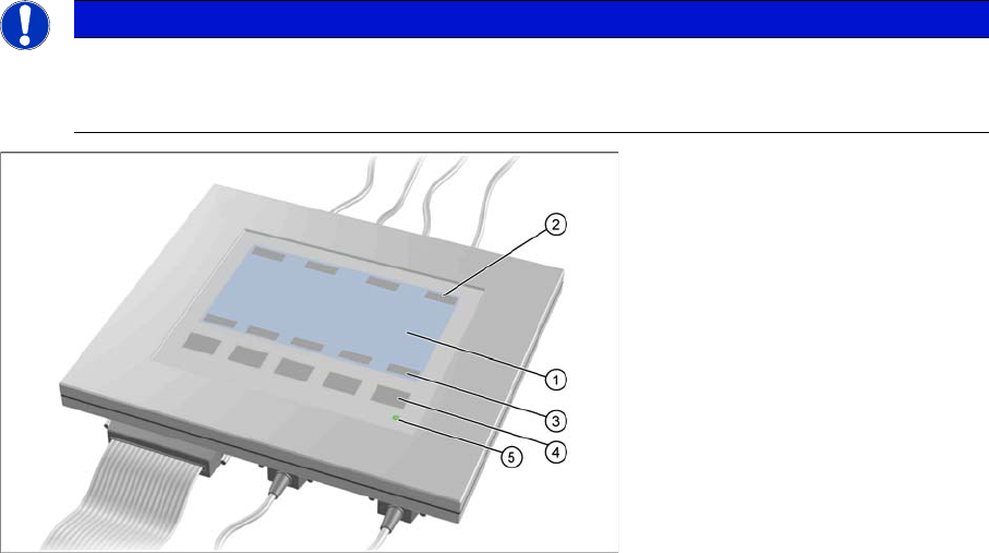
4.1 SIPLACE Axis Tester (SAT) [03002801-01]
SIPLACE Axis Tester (SAT) [03002801-01]
Axis tester - view from above
1. LCD display with 240 x 128 pixels, black-and-white display, with background illumination
The LCD display shows the menus and the recorded trigger, track and position signals. All relevant
parameters, such as
– Time basis,
– Time measurement values,
– Signal levels and
– Cursor positions with the corresponding time deviation values
are shown as alphanumerical data in the diagram of the measurement curves.
2. Dynamic function display of BNC socket arrangement on the LCD display
3. Dynamic function display of foil button arrangement on the LCD display
4. Five foil buttons for menu control
5. Green LED for displaying operation
NOTICE
A363, A364
The axis tester is designed for all machines with A363. This function is limited for machines
with A364.