00194440-10_SM_X-Series_Customer_en.pdf - 第280页
Settings Axis Control 5.2.3 C&P6/12 280 Service Manua l SIPLACE X Series Preparing Track Signals for St ar Axis Control (Example) Digital head axis track sign als 1. Track A 2. Track B NOTICE! The pulse width is depe…
Settings
5.2.3 C&P6/12 Axis Control
Service Manual SIPLACE X Series 279
Positioning time for C&P6
Positioning time for C&P6
5.2.3.2
5.2.3.2 Track Signals for Head Axes
Track Signals for Head Axes
The track signals play a greater role with the new drive concept for HF machines. They are responsible
for the precise positioning of the axes and are used as the only feedback signal in the closed-loop control
system, meaning that they have an important influence on the axis dynamics.
Overview
Oscilloscope settings
Measurement Setup
The head axis track signals can only be measured as digital signals i.e. the analog signals are converted
into digital signals in the read unit.
Axis Mode/range Positioning time
Star Axis continuous run / 1 star step 70 ms +/-3 ms
Z Absolute, free space / 685 digits 30 +/-3 ms
Z Light barrier, into calibration tool pocket / approx. 685 digits 30 +/-3 ms
DP 200 digits 38 ms +/-3 ms
DP 7200 digits 85 ms +/-3 ms
Axes Mechanical settings Oscilloscope diagram
Star 25x: resolution 1/1000° Digital track signal amplitude 3.6Vpp
Z nothing Digital track signal amplitude 3.6Vpp
DP Incremental encoder set to 1.5 mm, paral-
lel to the glass
Digital track signal amplitude 3.6Vpp
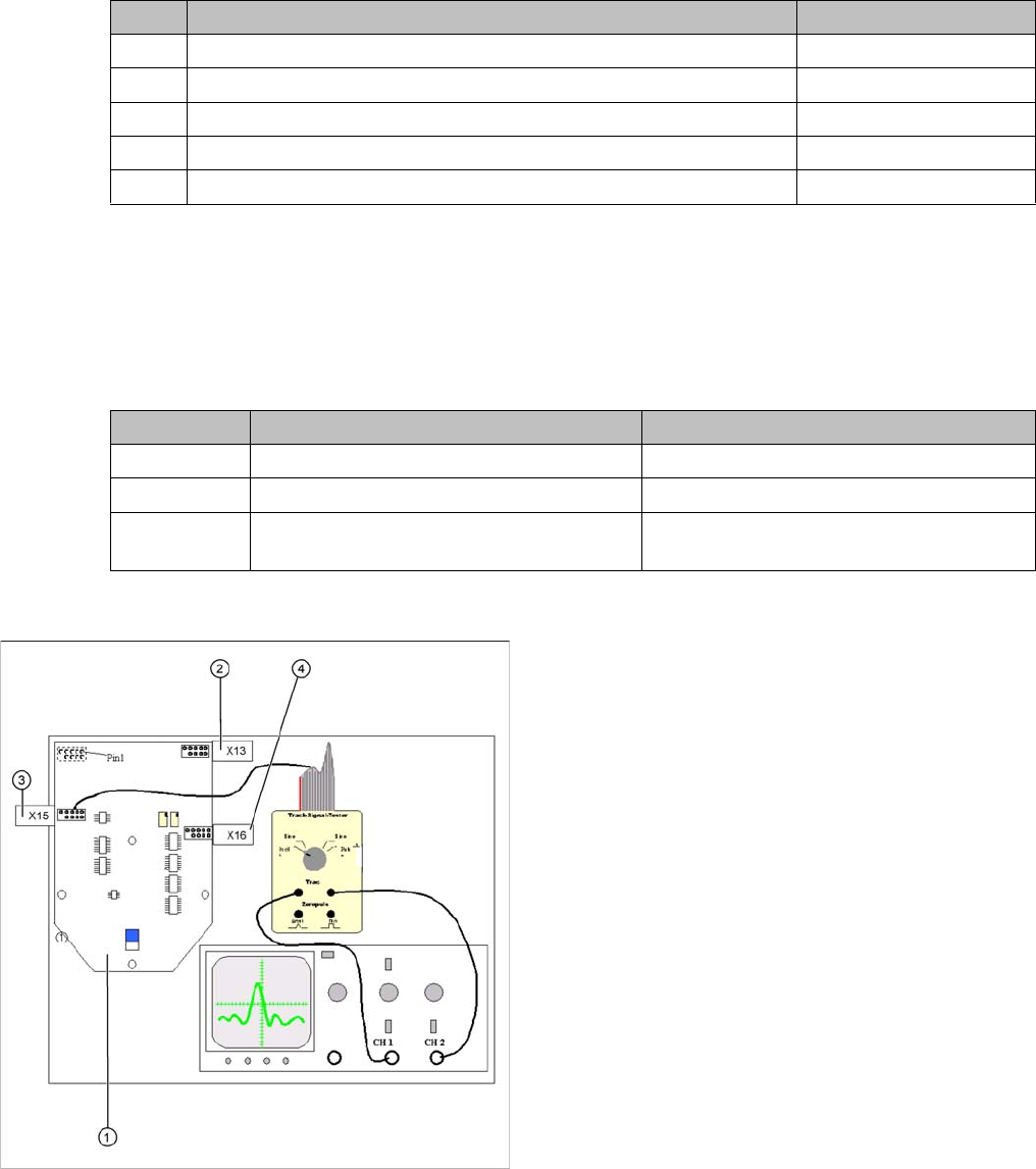
General measurement structure for checking track sig
-
nals
1. Intermediate distributor SP 6-12, digital
2. X13: track signals Z axis
3. X15: track signals star axis
4. X16: track signals DP axis
Assignment of connectors X13, X15, X16:
1. Ground
2. Track A
3. Track A
4. Ground
5. Track B
6. Track B
7. +5V
8. Track N
9. Track N
10. Removed
Settings
Axis Control 5.2.3 C&P6/12
280 Service Manual SIPLACE X Series
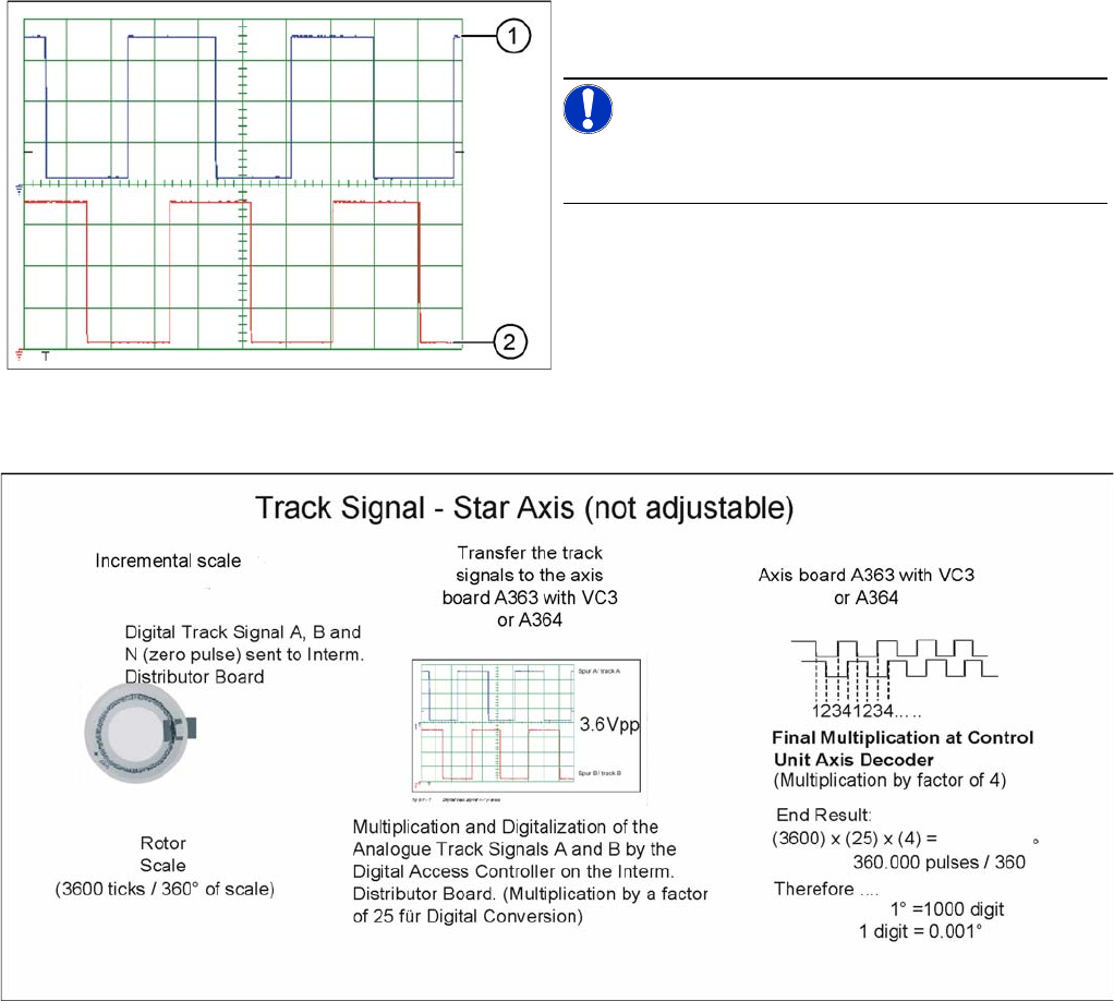
Preparing Track Signals for Star Axis Control (Example)
Digital head axis track signals
1. Track A
2. Track B
NOTICE!
The pulse width is dependent on the speed, the phase lo-
cation is dependent on the direction.
Settings
5.2.3 C&P6/12 Axis Control
Service Manual SIPLACE X Series 281
5.2.3.3
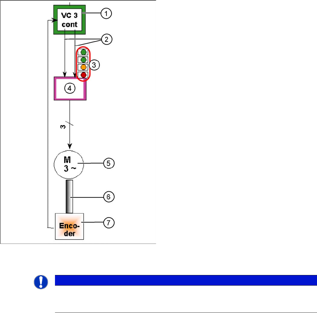
5.2.3.3 Star Axis Control System
Star Axis Control System
Checking the Star Axis Dynamics
Star axis control system
The star axis is driven via a 3-phase AC stepping motor
with an intermediate circuit voltage of 120 V. The activa-
tion is via two track signals (phase shift 120°) from the
VC3 controller Itarget "W" and I-target "U". The third
phase is calculated automatically.
1. Axis controller board A363 with VC3 controller (VC =
Velocity Commutation) or A 364
2. Control signals I target "W" and I target "U"
3. LEDs on servo amplifier:
4. Servo amplifier
5. 3 phase AC motor.
6. Between the motor and the incremental encoder
there is a fixed mechanical connection.
7. Incremental encoder: transmits the exact position of
the axis to the axis card. (The track signals are the
only feedback signals for the axes).
The servo board controls the motor directly.
NOTICE
Setting the axes
Before adjusting the axes, make sure that the machine has reached its operating temperature.
Switch the machine on at least 30 minutes before you begin work.