00194440-10_SM_X-Series_Customer_en.pdf - 第135页
Service Work 3.4.5 Replacing the C&P20A Head Placement heads Service Manual SIPLACE X Series 135 Removal ► Move the component tr o lley out of the machine. Installation ► Fit the new head. ► Reconnect the system to t…
Service Work
Placement heads 3.4.5 Replacing the C&P20A Head
134 Service Manual SIPLACE X Series
Installation
3.4.5
3.4.5 Replacing the C&P20A Head
Replacing the C&P20A Head
Parts, equipment and tools
▪ C&P20A head incl. camera [03062095-xx]
▪ C&P20A head without camera [03058420-xx]
▪ Torque screwdriver 100-500 Ncm [03078400-xx]
▪ Extension/straight TX20 [03073256-xx]
▪ Bit holder for Torque Vario-S screwdriver [03078706-xx]
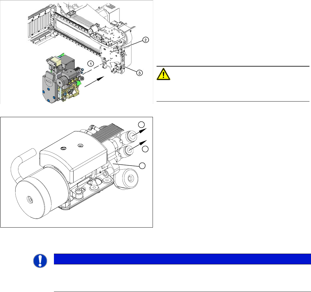
► Carefully move the head towards the head plate (3).
► Make sure that the parallel pins (2) on the head plate
slide into the holes drilled into the back part of the
head.
► Carefully push the head towards the head plate until
it lies flat against it.
► Fix the head with the four screws provided (1).
CAUTION!
Observe the torque
Tighten the screws with a torque of 2.7 Nm.
► Connect the compressed air hoses (1) to the pneu-
matic coupling on the vacuum generator (2).
► Reconnect to the electricity system.
► Use the SITEST program to calibrate the head.
1
1
2
NOTICE
Fast Head Exchange (FHE)
► Observe the instructions in section "3.4.1 Fast Head Exchange" [➙122] when exchanging
a head.
Service Work
3.4.5 Replacing the C&P20A Head Placement heads
Service Manual SIPLACE X Series 135
Removal
► Move the component trolley out of the machine.
Installation
► Fit the new head.
► Reconnect the system to the electrical and compressed air systems.
► After fitting the new head, this will need to be calibrated.
When using the FHE function it is sufficient from SW 703 onwards to perform a brief calibration since
the heads are already precalibrated.
► If there are any problems during the reference run (vacuum check), perform the "zero correction" for
the pressure control valve.
CAUTION
Do not damage the component sensor prisms!
The component sensor prisms, underneath the placement head, are easily damaged. Take
great care when dismantling the head!
► Protect the component sensor with a piece of hose. This is delivered with the placement
head or component sensor and should be stored in the service box for the machine, as it is
required for dismantling the head.
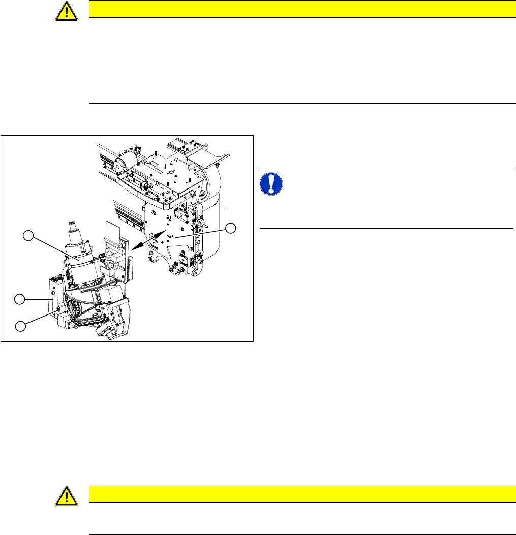
► Move the C&P20A head (1) into a position which al-
lows you best access.
NOTICE!
During the following removal work, take care not to dam-
age the component sensor prisms.
► Disconnect the C&P20A head from the compressed
air system.
► Disconnect the flat ribbon cables from the C&P20A.
► Loosen the two screws on the pressure control valve
(2).
► Remove the lower screw (3) on the pressure control
valve and swing the pressure control valve to one
side.
⇨ You can now access one of the fastening screws.
► Loosen all four M4 fastening screws with a long Allen
key.
► Carefully lift the head out of the locating pins on the
head plate (4).
2
4
1
3
CAUTION
Observe the torque
Tighten the M4x14 screws with a torque of 2.7 Nm.
Service Work
Placement heads 3.4.6 Checking the Cable Routing
136 Service Manual SIPLACE X Series
3.4.6
3.4.6 Checking the Cable Routing
Checking the Cable Routing
Cable routing on the SIPLACE D1/D2
Correct cable routing to and from the placement head is essential for long and accurate operation.
The high acceleration of the gantries can cause wear and damage to the connection leads.
▪ Covering free pins with plastic caps:
Flat ribbon cables and coax cables could be damaged by exposed pins, which is why all free pins
must be covered with plastic caps.
Use the dummy plugs [00368931-xx] for this.
▪ Optimum positioning of cable ties:
Cables ties should be positioned so that the cables can be fastened properly and are guided past
any sharp edges.
▪ Cable clamps for flat ribbon cables:
If run together, narrow flat ribbon cables should be placed under wider ones.
The cables should not be crossed under the clamp.
3.4.6.1
3.4.6.1 Cable Routing for Gantry Head Distributor Board
Cable Routing for Gantry Head Distributor Board
SIPLACE D1/D2 as example
CAUTION
Example illustration
In the event of service work, compare the arrangement of cables with that at another gantry.
The cable routing in this chapter is illustrated using the example of a D1/D2 machine, with the
intention of drawing your attention to the existing critical points on every machine.
CAUTION
Check the cable routing!
Incorrect cable routing or poor fixture of the connection cables can cause mechanical damage.
This can then lead to malfunctions, non-reproducable errors and machine standstill.
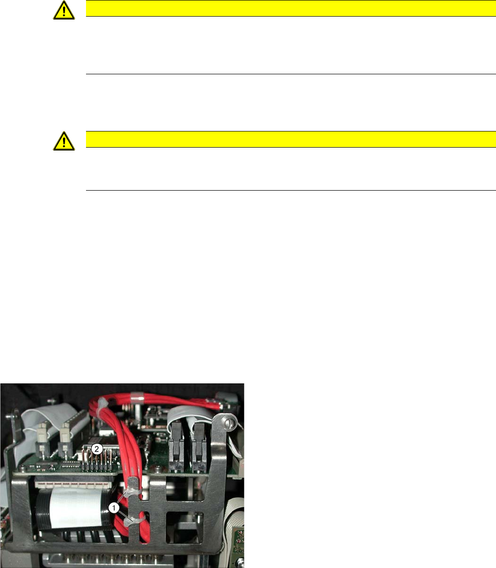
Position cable ties correctly.
The coax camera cables to the gantry head distributor
need to be fixed with cables ties at the side.
The diagram shows the optimum position (1) for two ca-
ble ties, so that the cables do not touch the connector
strip (2).
▪ However, the connector strip (2) should still be fitted
with a dummy plug for safety purposes.