00194440-10_SM_X-Series_Customer_en.pdf - 第188页
Service Work Modular PCB Conveyor System 3. 6.20 Replacing the Sensor for the Lower End Position on the Stopper (QC) 188 Service Manua l SIPLACE X Series 3.6.20 3 . 6 . 2 0 R e p la c in g t h e S e n s o r f o r t h e L…
Service Work
3.6.19 Replacing and Teaching the Sonar Sensor PXS240 (QC) [03069863-xx] Modular PCB Conveyor System
Service Manual SIPLACE X Series 187
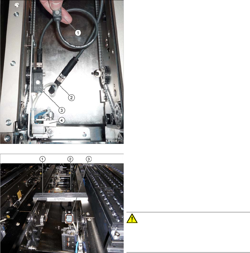
1. Programming cable for PXS240 ultrasonic sensor
2. Press-fit connection for the ultrasonic sensor
3. Ultrasonic sensor PXS240
4. PCB stopper
► Fit the new sonar sensor.
► Connect the programming cable between the sonar
sensor and the connection at the machine end.
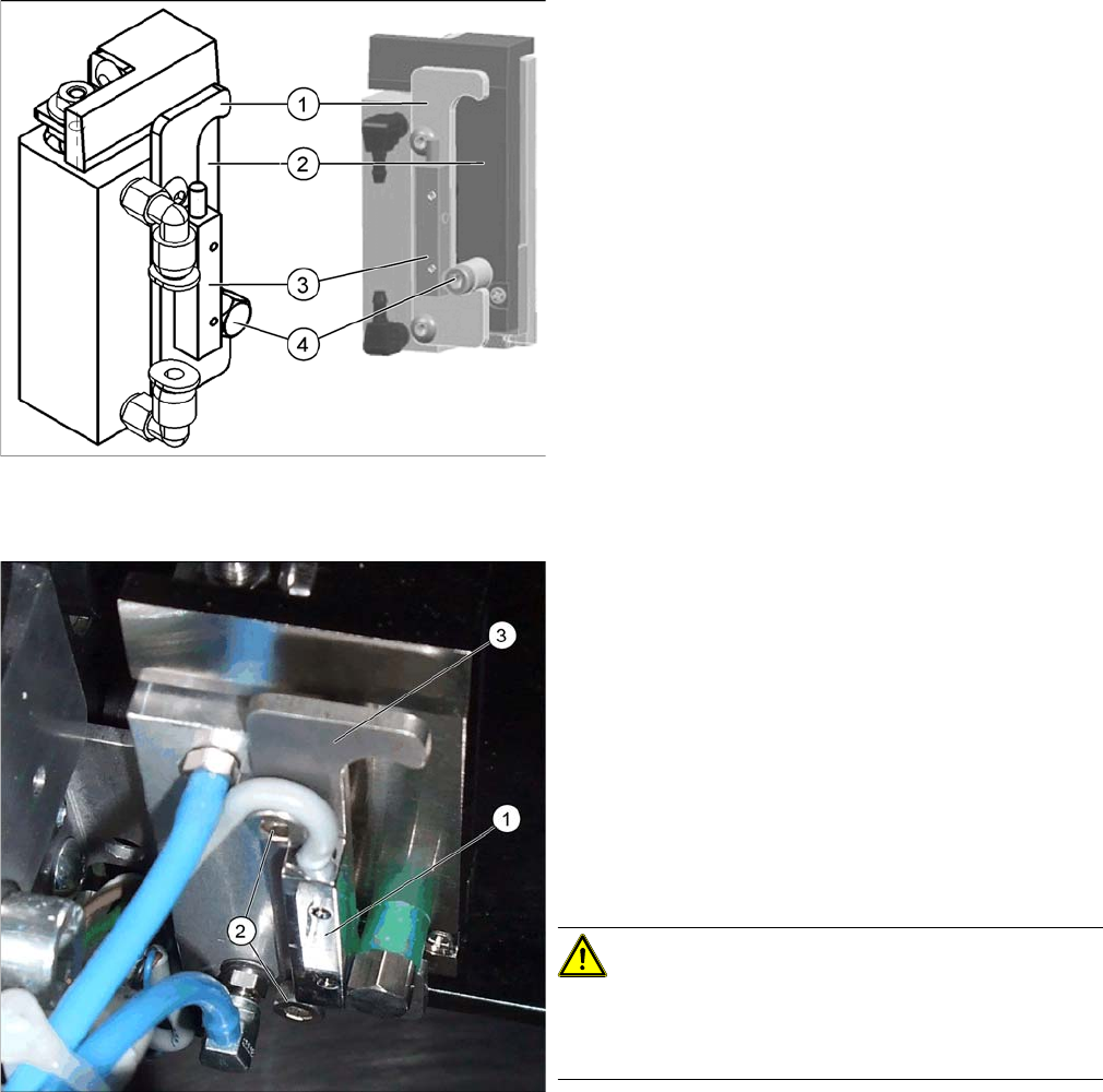
Fitted sonar sensor with programming cable and setting
gauge
1. Setting gauge
2. Programming cable (fitted)
3. LED on ultrasonic sensor
► The distance to the PCB is defined with the setting
gauge.
Position the setting gauge over the conveyor, so that
it is above the reception area of the ultrasonic sensor.
CAUTION!
Make sure that the gauge is used the right way round.
This gauge can be used for different conveyor types.
Make sure that the gauge is always used the right way
round.
► To teach, press the button on the programming cable
for approx. three seconds, until the LED on the sen-
sor (3) begins to flash.
The switching threshold is now set accordingly.
► Loosen the programming cable connections and con-
nect the sonar sensor directly to the connection at the
machine end.
► Remove the setting gauge.
Service Work
Modular PCB Conveyor System 3.6.20 Replacing the Sensor for the Lower End Position on the Stopper (QC)
188 Service Manual SIPLACE X Series
3.6.20
3.6.20 Replacing the Sensor for the Lower End Position on the Stopper (QC) [03066803-xx]
Replacing the Sensor for the Lower End Position on the Stopper (QC) [03066803-xx]
Overview
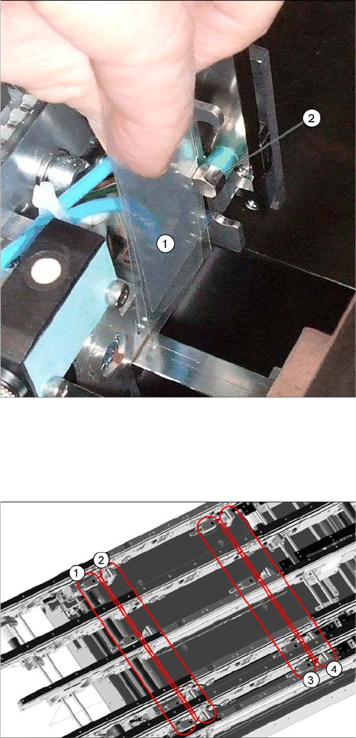
Removal/installation
1. Stroke limitation rail
2. Stop rail
3. Sensor lower end position stopper [03066803-xx]
4. Stopper bolt
1. Sensor for lower end position on stopper
2. Fastening screws for stop rail
3. Stop rail
► Switch off the machine.
► Loosen the two screws (2) fastening the stop rail.
► Loosen the two screws fastening the sensor to the
back of the stop rail.
► Unthread the sensor connection cable. If you need to
loosen cable clamps, mark their positions before re-
moval.
CAUTION!
Do not pull out the Z axis!
Do not pull the Z axis of the stopper too far out at the top,
otherwise the bearings could fall out!
► Fit the new sensor onto the stop rail. Fit the stop rail
but do not tighten the fastening screws (2) complete-
ly.
Service Work
3.6.21 Replacing and Setting the Stopper (QC) [03069271-xx] Modular PCB Conveyor System
Service Manual SIPLACE X Series 189
3.6.21
3.6.21 Replacing and Setting the Stopper (QC) [03069271-xx]
Replacing and Setting the Stopper (QC) [03069271-xx]
Overview
► Set the distance between the sensor and the stopper
bolts (2) over the entire length with a feeler gauge (1)
to 0.4 mm and then tighten the screws fastening the
stop rail.
► Reconnect the sensor and fasten the cable with cable
ties.
► Switch on the machine
Quad lane conveyor – in the placement area
1. Stopper in input conveyor (four)
2. Stopper in placement area (four)
3. Proximity switches in input conveyor (four)
4. Proximity switches in placement area (four)
The stopper units in the input conveyor need to be dis-
mantled before you can replace spare parts. The stopper
units in the two placement areas may only be dismantled
from the assembly brackets if their positions are then re-
set with a setting gauge, after fitting. The screws need to
be sealed with locking varnish again.