00194440-10_SM_X-Series_Customer_en.pdf - 第197页
Service Work 3.7.2 Replacing the X Series Feeder Contro l Unit (FCU) [0302006 8-xx] X-Series COT Inser t Service Manual SIPLACE X Series 197 3.7.2 3 . 7 . 2 R e p la c in g t h e X S e r ie s F e e d e r C o n t r o l U …
Service Work
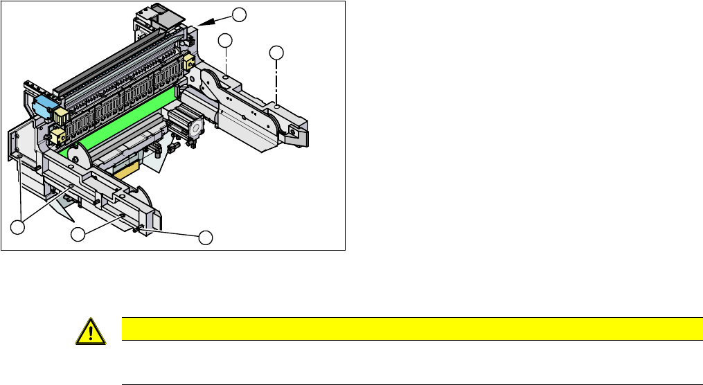
X-Series COT Insert 3.7.1 Replacing the X-Series COT Insert [03015680-xx]
196 Service Manual SIPLACE X Series
► Move the COT insert into its final position (to the previously marked installation position).
Take care not to damage the cables and hoses.
► Loosely screw in the fitting screw and the fastening screws.
► Tighten the fitting screw first.
► Tighten the fastening screws.
► Fit the nozzle changer.
See also
6.4.1 Control Unit on Cutter [ ➙ 376]
6.4.2 Control Unit on Cutter (CAN Nodes) [ ➙ 377]
► Loosen the screws fastening the COT insert (1).
► Loosen the fitting screw (2) on the inside of the ma-
chine.
► Lift the complete COT insert out of the machine and
place it on a suitable surface (four wooden blocks
etc.).
► Make sure that you do not damage any valves, con-
nection cables, hoses etc.
► Attach the fit-up aid to the new COT insert and lift it
into the machine, with the help of the lifting device.
► Reconnect all cables.
1
1
1
1
2
1
CAUTION
Observe the specified order!
The fitting screw must be tightened first, before you tighten the other fastening screws.
Service Work
3.7.2 Replacing the X Series Feeder Control Unit (FCU) [03020068-xx] X-Series COT Insert
Service Manual SIPLACE X Series 197
3.7.2
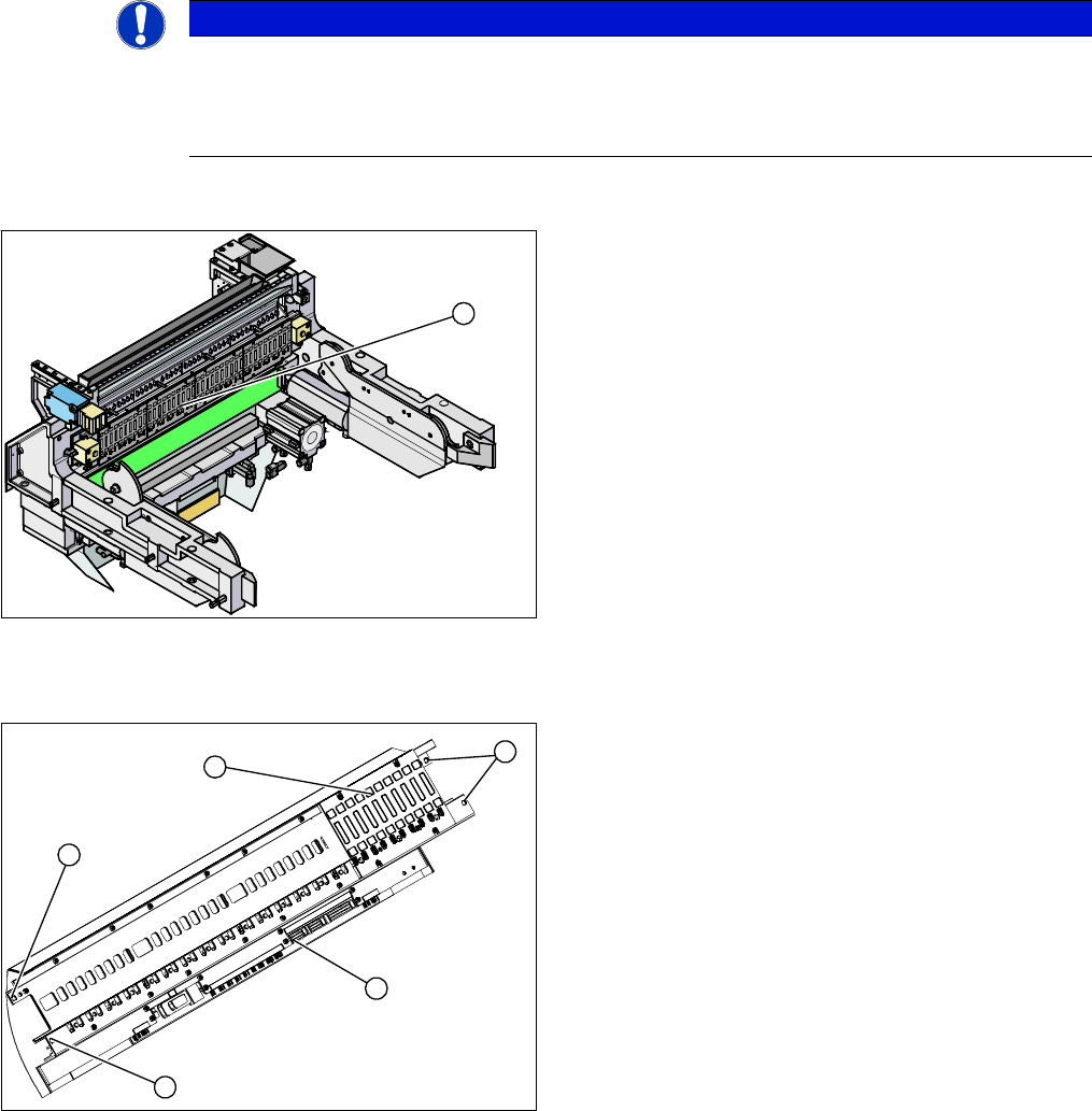
3.7.2 Replacing the X Series Feeder Control Unit (FCU) [03020068-xx]
Replacing the X Series Feeder Control Unit (FCU) [03020068-xx]
Overview
Removal/installation
► Remove the earth terminal.
► Place the connection cable in the recess and carefully push in the new FCU. Make sure you do not
pinch any cables.
► Pull the ends of the cables out from under the terminal strip.
► If necessary, adjust the jumper on the FCU (see "6.5.1 Connecting assy FCU [03059783-xx]"
[ ➙ 378]).
► Fix the FCU into place, with the four fastening screws.
► Plug in all electrical connections as labeled on the terminal strip.
NOTICE
FCU replacement
When replacing an X-FCU on X-Series machines with a manufacturing date before 07/2010,
you need to use a retrofit kit. For more details, read the technical information "Installing a new
X-FCU / X-Series [03059623-xx] as a spare part" [DE: TI2010-08D01] [EN: TI2010-08E01].
1. Feeder control unit (FCU)
The feeder control unit (FCU) is installed at the locations
in the component trolley feed device.
1
1. Complete FCU
2. Terminal strip
3. 4 x fastening screws
► Label all cables and the positions of the connectors
plugged into the terminal strip (2) of the FCU (1).
► Unplug all electrical connections from the terminal
strip (2) of the FCU (1).
► Loosen the four screws (3) holding the FCU in place.
► Carefully lever the FCU out of the locating pins.
3
3
1
3
2
Service Work
X-Series COT Insert 3.7.3 Replacing the 40-Fold Feeder Unlock Device [03011582-xx]
198 Service Manual SIPLACE X Series
3.7.3
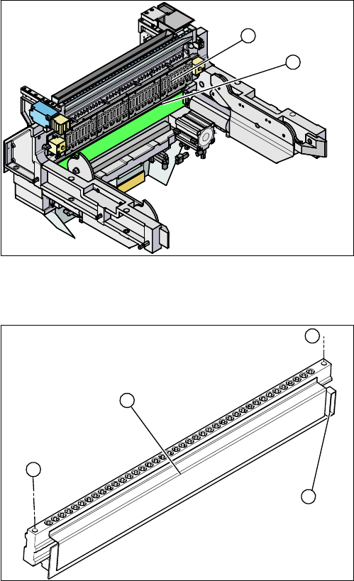
3.7.3 Replacing the 40-Fold Feeder Unlock Device [03011582-xx]
Replacing the 40-Fold Feeder Unlock Device [03011582-xx]
Overview
Removal/installation
1. Feeder unlocking device (under the FCU)
2. Feeder control unit (FCU)
The feeder unlocking device is installed at the locations
in the COT insert.
2
1
1. Two fastening screws
2. Complete feeder unlocking device
3. Connector for flat ribbon cable
► Unplug the flat ribbon cable from the connector (3).
► Loosen the two fastening screws (1) and remove the
complete unit (2).
► Lift up the feeder unlock device by its fixtures and pull
out the flat ribbon cable from the side of the connector
(3).
► Connect the flat ribbon cable.
► Carefully press the feeder unlock device towards the
back and insert the fastening screws (1).
► Make sure that you do not pinch or damage the ca-
bles run at the back (connected to the FCU).
1
1
3
2