00194440-10_SM_X-Series_Customer_en.pdf - 第356页
Settings Other Settings 5.6.5 Calibration 356 Service Manua l SIPLACE X Series 5.6.5.2 5 . 6 . 5 . 2 C a lib r a t io n P r o c e d u r e Calibration Procedure C&P calibration procedure
Settings
5.6.5 Calibration Other Settings
Service Manual SIPLACE X Series 355
5.6.5
5.6.5 Calibration
Calibration
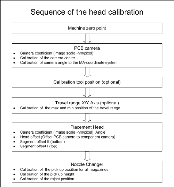
Overview
This calibration step first measures the component camera. This determines the relationship of "camera
pixel size to resolution of machine measuring system (X,Y)", the "camera center point in X and Y direc-
tion" and the "torsion angle of the CCD sensor in the camera". This is following by determining the head
offset and the segment offsets for the top and bottom.
▪ Head offset: the head offset is the distance between the PCB camera and the nozzle (segment 1).
The target is a fixed value (X=0 and Y=-105 mm), to which an offset value (from the head calibration)
is added.
▪ Segment offset top: the top segment offset involves turning the calibration tool in the component
camera in 0, 90, 180 and 270° steps. The value determined is that of the rotating center of the nozzle
tip in relation to the component camera center in the X and Y direction.
▪ Segment offset bottom: the bottom segment offset involves recording and measuring the calibration
tool in the 0, 90, 180 and 270° positions. The value determined is that of the rotating center point of
the nozzle tip when the Z axis is extended in relation to the PCB camera. Segment 1 forms the ref-
erence (X=0, Y=0) to the other segments.
5.6.5.1
5.6.5.1 Calibrating the Heads and Cameras
Calibrating the Heads and Cameras
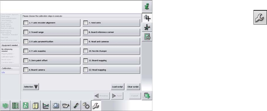
► Switch over to the operator level Service (Customer).
► Switch over to the Service menu and select Ma-
chine calibration or Automatic calibration (depending
on SW version).
► Select 8. Head and cameras and click on Next.
► On the next page, select the gantries on which the
heads to be calibrated are located and then click on
Next.
► The next step is to check the calibration conditions
(nozzle, calibration tool etc.). Follow the instructions
provided.
After this step, calibration will begin. All required interme-
diate steps (head height etc.) will be performed automat-
ically.
Settings
Other Settings 5.6.5 Calibration
356 Service Manual SIPLACE X Series
5.6.5.2
5.6.5.2 Calibration Procedure
Calibration Procedure
C&P calibration procedure

Settings
5.6.6 DIP Switch for Camera Types 25 and 33 Other Settings
Service Manual SIPLACE X Series 357
5.6.6
5.6.6 DIP Switch for Camera Types 25 and 33
DIP Switch for Camera Types 25 and 33
Setting
► Switch off the machine, disconnect it from the power supply and secure it to prevent unauthorized
reactivation. Observe the instructions in section "1.2 Preparatory Work..." [ ➙ 15].
► Remove the camera upper part and the cover on the lower part, to gain access to the DIP switches.
► Set the DIP switches. (see below)
► Fit all parts by following the above instructions in the reverse order.
DIP switch
Boards with version status 01 and 02 are fitted with a TQ module. In this case, the DIP switching block
is 8 pin.
Boards with version status 03 or higher do not have a TQ module. In this case, the DIP switching block
is 6 pin.
Version state 01 and 02: DIP switch settings (8 pin)
* Not all gantries may be available, depending on the machine type.
Version state 03 and higher: DIP switch settings (6 pin)
* Not all gantries may be available, depending on the machine type.
See also
6.7.1 Vision LED driver VLT 33 [03039244-xx] [ ➙ 381]
S Setting for gantry* Comments
1 2
1OFFOFFBootstrap
2OFFOFFReset
3OFFOFFGantry ID 0
4OFFONGantry ID 1
5OFFOFFTest
6OFFOFFCAN terminator
7ON ON CAN speed: ON: 1 Mbit/s, OFF: 500 KB/s
8 xx xx OFF: FC camera (type 25), ON: IC camera (type 33)
S Setting for gantry* Comments
1 2
1OFFOFFReset
2OFFOFFGantry ID 0
3OFFONGantry ID 1
4 x x x x LED: This switch is delivered with a fixed presetting.
Do not change this setting!
5OFFOFFCAN terminator
6 xx xx OFF: FC camera (type 25), ON: IC camera (type 33)