00194440-10_SM_X-Series_Customer_en.pdf - 第293页
Settings 5.2.4 C&P20 Axis Control Service Manual SIPLACE X Series 293 5.2.4 5 . 2 . 4 C & P 2 0 C&P20 5.2.4.1 5 . 2 . 4 . 1 O v e r v ie w o f A x is C o n t r o l f o r S t a r , Z a n d D P A x is Overview …
Settings
Axis Control 5.2.3 C&P6/12
292 Service Manual SIPLACE X Series
C&P6 - for DP axis, 200 digits
C&P6 - for DP axis, 7200 digits
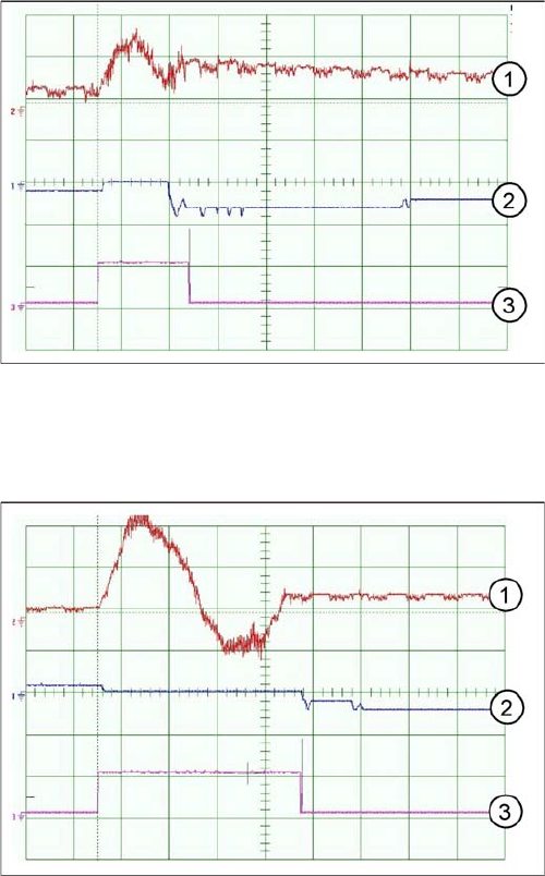
Travel curves for DP axis, 200 digits for C&P6
1. Current target value: 100 mV/Div
2. Position deviation: 500 mV/Div
3. End signal
Time basis: 20ms/Div
Path: 200 digits
Travel curves for DP axis, 90 degrees rotation, C&P6
1. Current target value: 200 mV/Div
2. Position deviation: 500 mV/Div
3. End signal
Time basis: 20ms/Div
Path: 7200 digits
Settings
5.2.4 C&P20 Axis Control
Service Manual SIPLACE X Series 293
5.2.4
5.2.4 C&P20
C&P20
5.2.4.1
5.2.4.1 Overview of Axis Control for Star, Z and DP Axis
Overview of Axis Control for Star, Z and DP Axis
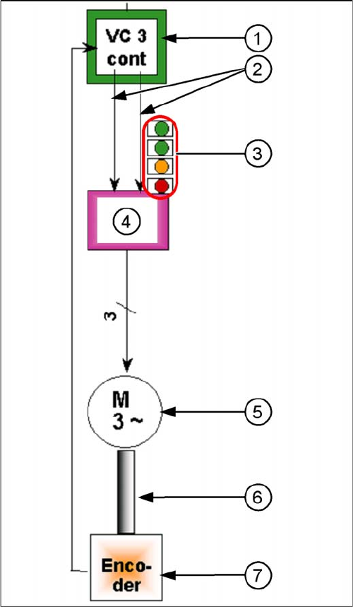
Example: axis control star axis
The closed-loop control system for control of the head
axes consists of the following parts. The differences be-
tween the head axes will be explained later in this chap-
ter.
▪ Axis card A363 with VC3 controller or A364
▪ Servo card (SDS)
▪ Motor
▪ Measurement system (incremental scale and encod-
er)
1. Axis controller board A363 with VC3 controller (VC =
Velocity Commutation)
2. Control signals I target "W" and I target "U"
3. LEDs on servo amplifier:
4. Servo amplifier
5. 3 phase AC motor.
6. Between the motor and the incremental encoder
there is a fixed mechanical connection.
7. Read unit: transmits the exact position of the axis to
the axis card. The track signals are the only feedback
signals for the axes.
The servo board controls the motor directly.
Settings
Axis Control 5.2.4 C&P20
294 Service Manual SIPLACE X Series
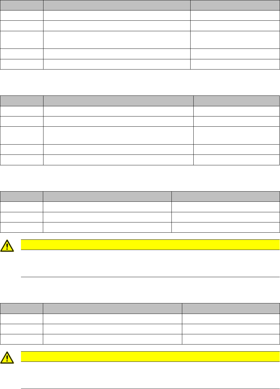
Positioning Time for C&P12 DLM2
Positioning Time for C&P12 DLM2
Positioning Time for C&P6 DLM2
Positioning Time for C&P6 DLM2
Positioning Time for C&P20
Positioning time for C&P20 – SITEST (with service password)
Positioning Time for C&P20A
Positioning time for C&P20 – SITEST (with service password)
Axis Mode/range/ Positioning time
Star Axis continuous run/1 step (30°) 46 ms +/-3 ms
Z Absolute, free space / 685 digits 24 ms, -1 ms
Z Light barrier, into calibration tool pocket / approx. 685
digits
approx. 24 +/-3 ms
DP 100 digits 13 ms +/-3 ms
DP 3600 digits 43ms +/-3ms
Axis Mode/range/ Positioning time
Star Axis continuous run/1 step (60°) 70 ms +/-3 ms
Z Absolute, free space / 685 digits 30 +/-3 ms
Z Light barrier, into calibration tool pocket / approx. 685
digits
30 +/-3 ms
DP 200 digits 38 ms +/-3 ms
DP 7200 digits 85 ms +/-3 ms
Axis Mode/range/ Positioning time
Star Axis continuous run/1 step (18°) 28.5 ms +/-0.5 ms
Z Absolute, free space /20,000 digits 10000 µm Target 16 ms
DP Rotation of 180° Max. 300 ms
CAUTION
Gantry in calibration tool position
When checking the C&P20 Z axis dynamics, the gantry must be over the calibration tool posi-
tion.
Axis Mode/range/ Positioning time
Star Axis continuous run/1 step (18°) 28.5 ms +/-0.5 ms
Z Absolute, free space /20,000 digits 10000 µm Target 16.7 ms+/-1ms
DP Rotation of 180° Max. 300 ms
CAUTION
Positioning times
The positioning times in the table do not apply during the placement or pickup procedures.
These times refer to the continuous axis run of an axis.