00194440-10_SM_X-Series_Customer_en.pdf - 第207页
Service Work 3.8.5 Replacing the Docked Component Trolle y Round Cylinder [03 002255-xx] COT Inser t HF R2 Service Manual SIPLACE X Series 207 Removal/installation ► Place the COT insert dow n in a suitable position. CAU…
Service Work
COT Insert HF R2 3.8.4 Replacing the Control Valve [03005828-xx]
206 Service Manual SIPLACE X Series
3.8.4
3.8.4 Replacing the Control Valve [03005828-xx]
Replacing the Control Valve [03005828-xx]
Removal/Installation
3.8.5
3.8.5 Replacing the Docked Component Trolley Round Cylinder [03002255-xx]
Replacing the Docked Component Trolley Round Cylinder [03002255-xx]
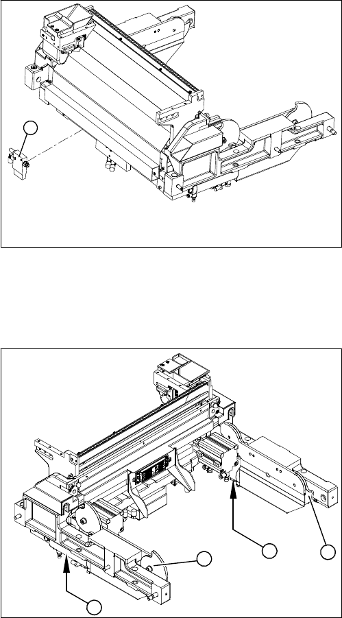
Overview
1. Control valve
► Remove the complete COT insert from the machine
and place it on a suitable surface.
► Unplug the electricity and compressed air cables
from the control valve (1).
► Loosen the fastening screws and remove the control
valve (1).
► Install the new control valve (1).
► Reconnect to the electrical and compressed air sys-
tems.
► Fit the complete COT insert in the machine.
1
1. Docked component trolley round cylinder
2. Cam disc unit
► Remove the complete COT insert from the machine.
1
2
2
1
Service Work
3.8.5 Replacing the Docked Component Trolley Round Cylinder [03002255-xx] COT Insert HF R2
Service Manual SIPLACE X Series 207
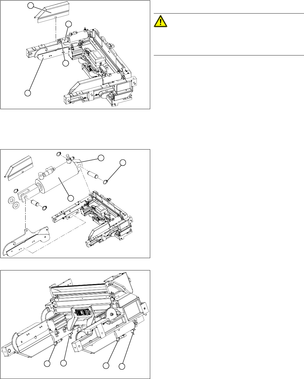
Removal/installation
► Place the COT insert down in a suitable position.
CAUTION!
Risk of damage!
Make sure that you do not damage any valves, connec-
tions or cables.
► Mark the allocation of the compressed air connec-
tions and disconnect them from the round cylinder.
► Remove the cylinder cover (1).
► Undo the circlip (2) on the fork head (3) with a suitable
pair of circlip pliers
► Carefully knock the shafts out of their guides. Make
sure that you do not lose the two shim rings.
► Loosen the screws fastening the cam disk unit (4)
and carefully lever it out of the locating pins.
► Undo the circlips (1) on the axes and gently knock the
shafts (2) out of the articulated joint.
► Remove the round cylinder (3).
► First install the new round cylinder and then the other
parts in reverse order.
► Plug in the compressed air connections in the correct
allocation.
1. Speed adjustment valve – docked
2. Speed adjustment valve - undocked
► Fit the complete COT insert into the machine again.
► Set the round cylinder speed so that the left and right
cam disk unit run parallel to one another.
(time needed to move in/out approx. 2 s)
► Adjust the setting screw on each docking (1) and un-
docking (2) valve accordingly.
This ensures that the component trolley is not distort-
ed when moved in.
1
3
2
4
1
3
2
1
2
1
2
Service Work
COT Insert HF R2 3.8.6 Replacing the Empty-Tape Duct Assembly [03003725-xx]
208 Service Manual SIPLACE X Series
3.8.6
3.8.6 Replacing the Empty-Tape Duct Assembly [03003725-xx]
Replacing the Empty-Tape Duct Assembly [03003725-xx]
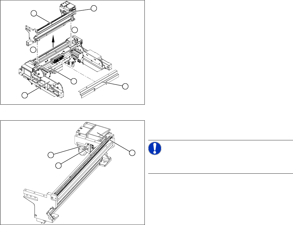
Removal/installation
1. COT insert assembly
2. Cutter, complete
3. Empty-tape duct assembly
► Remove the complete COT insert from the machine.
► Loosen the screws fastening the centering bar (4).
► Remove the centering bar (4).
► Mark the position of the sensors (6) (reed contacts)
and remove these from the reject container.
► Loosen the screws (5) holding the empty-tape duct
assembly (3).
► Carefully lift the empty-tape duct (3) out of the COT
insert (1).
► Fit the sensors (1) (reed contacts) for the reject con-
tainer (2).
NOTICE!
These sensors are installed in different positions, accord-
ing to the configuration of the machine.
► Fit the empty-tape duct and the centering bar.
1
3
6
5
4
5
2
1
1
2