00194440-10_SM_X-Series_Customer_en.pdf - 第317页
Settings 5.3.1 Setting the Height of the Nozzle Changer for the C&P20A No zzle Changer Setting Service Manual SIPLACE X Series 317 5.3.1.1 5 . 3 . 1 . 1 N o z z le R e je c t U n it Nozzle Reject Unit The C&P20A …
Settings
Nozzle Changer Setting 5.3.1 Setting the Height of the Nozzle Changer for the C&P20A
316 Service Manual SIPLACE X Series
5.3
5.3 Nozzle Changer Setting
Nozzle Changer Setting
5.3.1
5.3.1 Setting the Height of the Nozzle Changer for the C&P20A
Setting the Height of the Nozzle Changer for the C&P20A
Parts, equipment and tools
▪ Measuring scale
▪ NC shim plate [03021079-xx]
Overview
Setting
Setting the nozzle changer for C&P20A
1. Measuring scale
2. Top edge of the X axis lower linear guide
3. Fitting surface for nozzle changer
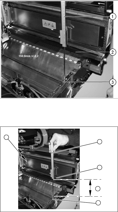
In order to guarantee the safety gap between the head
(component sensor) and nozzle changer, the contact sur-
face of the nozzle changer on the docking unit is set to a
distance of 150.0 mm +/-0.2 mm to the X axis linear guid-
ance, with a measuring scale. The height of the fitting sur-
face on the docking unit is adjusted with the help of shim
rings. The nozzle changer can then be fitted.
1. Measuring scale
2. Top edge of the X axis lower linear guide
3. Values to be set (150 +/- 0.2 mm)
4. Nozzle changer contact surface
► During the following inside measurement, make sure
that the tip of the measuring scale does not tough the
magnetic strip, as this might scratch it!
► Position the measuring scale (1) on the top edge of
the X axis lower linear guide (2) and measure the dis-
tance to the nozzle changer contact surface (4).
► Hold the measuring scale vertically (1).
► The setting value (4) is 150 +/-0.2 mm.
Add or remove shims as required.
► Repeat this measurement on the inside of the gantry
(5).
► Calibrate the position of the nozzle changer.
5
1
4
3
2
Settings
5.3.1 Setting the Height of the Nozzle Changer for the C&P20A Nozzle Changer Setting
Service Manual SIPLACE X Series 317
5.3.1.1
5.3.1.1 Nozzle Reject Unit
Nozzle Reject Unit
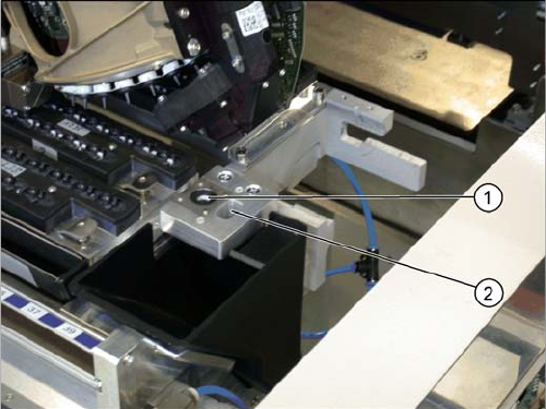
The C&P20A reject unit is equipped with a device for
checking the seat of the nozzles on the segments.
The height of the nozzle reject unit must be set to 140.0
+\-0.3 mm. Measurement follows the same procedure as
that for the nozzle changer (see "5.3.1 Setting the Height
of the Nozzle Changer for the C&P20A" [ ➙ 316]).
1. Check nozzle seat
2. Nozzle reject
Settings
Nozzle Changer Setting 5.3.2 Jumpers on the Nozzle Changer
318 Service Manual SIPLACE X Series
5.3.2
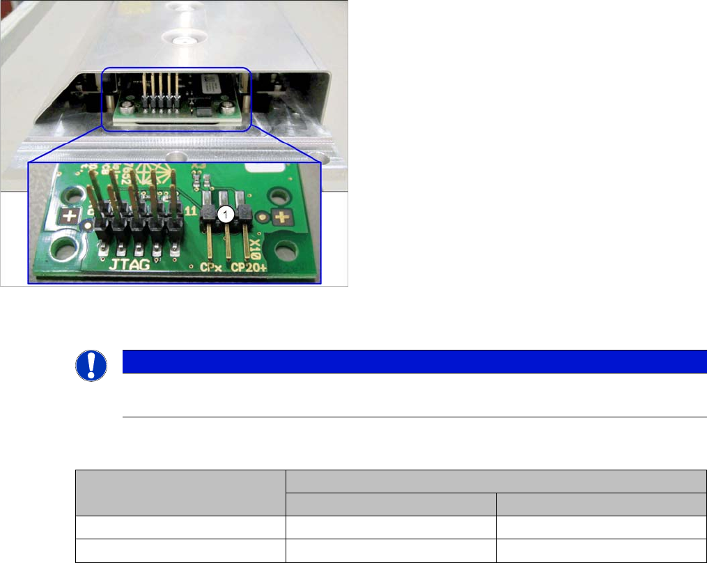
5.3.2 Jumpers on the Nozzle Changer
Jumpers on the Nozzle Changer
The jumper X10 needs to be set at the following nozzle changers:
▪ Nozzle changer basic structure CPx/all assembly - short [03103649-xx]
▪ Nozzle changer basic structure CPx/all assembly - long [03103514-xx]
Overview
Setting
► Set the correct value for your head type and software.
Nozzle Changer CP20P - Jumper X10
Jumper X10
See also
6.6.2 Nozzle Changer Main Board C&P20P [03107652-xx] [ ➙ 380]
1. Jumper X10
NOTICE
Before installation
Due to the design, this setting must be performed before installation in the machine.
Head Jumper position
SW <= 706.x SW >= 707.x
CPx, DLM 1-2 1-2 or 2-3
C&P20 P --- 2-3 (factory settings)