00194440-10_SM_X-Series_Customer_en.pdf - 第131页
Service Work 3.4.3 Replacing the Twin Head [03001095Sxx] Placement heads Service Manual SIPLACE X Series 131 Conversion to another installation height 3.4.3 3 . 4 . 3 R e p la c in g t h e T w in H e a d [ 0 3 0 0 1 0 9 …
Service Work
Placement heads 3.4.2 Replacing the CPP Head
130 Service Manual SIPLACE X Series
3.4.2.1
3.4.2.1 Preparing the Head for the Installation Height
Preparing the Head for the Installation Height
Overview
CAUTION
Different heights
The placement head can be installed at two different heights. CPP_L corresponds to a compo-
nent height of six mm. CPP_H corresponds to a component height of 11.5 mm.
If the CPP head is used in a placement area with stationary camera, TwinHead or WPC, it may
only be used in the upper position.
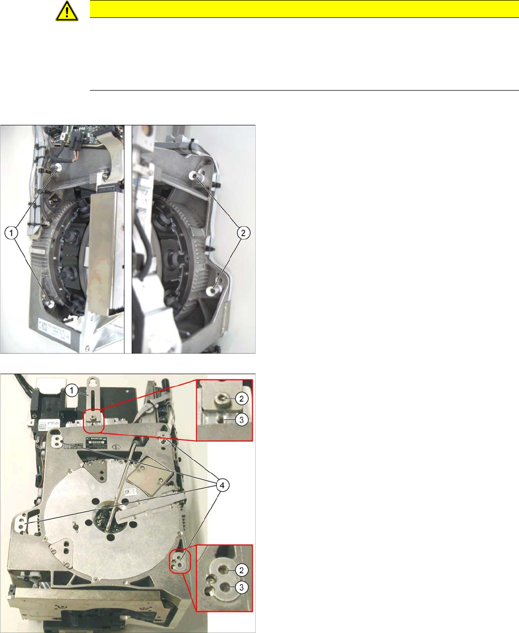
1. Fastening screws on the left side
2. Fastening screws on the right side
This diagram shows the fastening screws in the "head at
top" position.
1. Holding bracket
2. "Head at bottom" position
3. "Head at top" position
4. Fixture holes with bushings
Service Work
3.4.3 Replacing the Twin Head [03001095Sxx] Placement heads
Service Manual SIPLACE X Series 131
Conversion to another installation height
3.4.3
3.4.3 Replacing the Twin Head [03001095Sxx]
Replacing the Twin Head [03001095Sxx]
The TwinHead consists of two identical Twin segments, which are fitted at an angle of 180° to one an-
other.
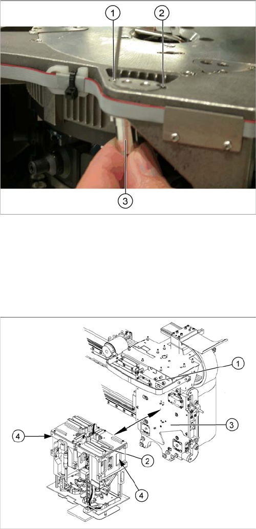
Removal/installation
1. Drilling for the fastening screw of the bushing in "head
at bottom" position
2. Drilling for the fastening screw of the bushing in "head
at top" position
3. Bushing
All four bushings and the holding bracket must either be
fixed in top or bottom position.
Proceed as follows when replacing the bushings:
► Undo the fastening screws of the bushings.
► Insert the bushings in the correct position and re-
tighten them.
► Perform these steps for all four fastening bushings
and the holding bracket of the head.
► Move the component trolley out of the machine.
► Move the TwinHead into a position which allows you
best access.
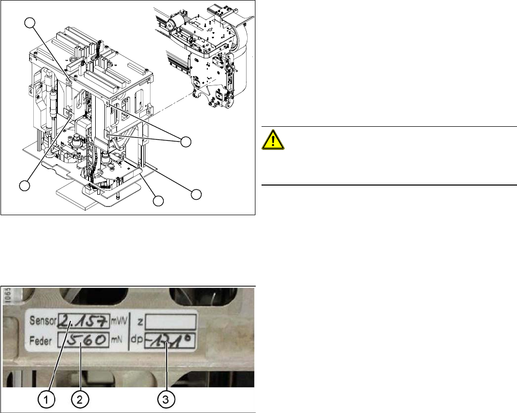
► Loosen the pneumatic connection from the Twin-
Head vacuum generator to the pneumatic
distributor (1).
► Disconnect the exhaust air silicone hose from the
TwinHead vacuum generator (4).
► Unplug the pneumatic connection from the pneumat-
ic distributor (1) to the TwinHead return cylinder.
► Unplug the flat ribbon cable from the head main
board (2) on the TwinHead.
Each module is fixed with four screws to the head
plate (3) and is positioned with two pins.
Service Work
Placement heads 3.4.3 Replacing the Twin Head [03001095Sxx]
132 Service Manual SIPLACE X Series
Entering the force values for the new module
► Loosen the screws (1) fastening the cover (3).
► Loosen the four M4x14 fastening screws (2) with a
long Allen key.
► Pull the module out of the locating pins.
► Make a note of the force values for the new module.
These force values can be found on a label at the side
of the module.
► Fit the new module.
CAUTION!
Observe the torque
Tighten the M4x14 screws with a torque of 2.7 Nm.
► Reconnect the system to the electrical and com-
pressed air systems.
► Fit the cover (3).
2
2
1
3
2
► Start the SITEST program and enter the new force
values for this module.
► To do this, select the TwinHead axis function in the
SITEST program and activate the appropriate seg-
ment (module).
► Activate the Z axis radio button and select the Param-
eter... button.
► Enter the values for the force sensor adjust value and
the spring bias.
► Use the SITEST program to calibrate the TwinHead.
⇨ Head height
⇨ Camera IC
⇨ Head calibration