00194440-10_SM_X-Series_Customer_en.pdf - 第87页
Service Work 3.3.2 Replacing the End Positi on / Reference Point Proximity Sw itch for the X axis [03004109-xx] Gantries Service Manual SIPLACE X Series 87 3.3.2 3 . 3 . 2 R e p la c in g t h e E n d P o s it io n / R e …
Service Work
Gantries 3.3.1 Replacing the X Axis Incremental Encoder
86 Service Manual SIPLACE X Series
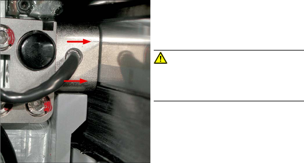
Casting marks on the incremental encoder
► You must set the exact height to the scale.
► Align the incremental encoder, using the two casting
marks (arrows), which mark the read area.
► Tighten the fastening screws.
► Reconnect to the electricity supply (X15 or X24).
CAUTION!
Check how the cables are run!
Make sure that the axes can be moved without damaging
the cables.
Fasten the cables with cable ties.
► Move the gantry into the end stopper and check that
the buffer does not come into contact with the cable.
Service Work
3.3.2 Replacing the End Position / Reference Point Proximity Switch for the X axis [03004109-xx] Gantries
Service Manual SIPLACE X Series 87
3.3.2
3.3.2 Replacing the End Position / Reference Point Proximity Switch for the X axis [03004109-xx]
Replacing the End Position / Reference Point Proximity Switch for the X axis
[03004109-xx]
NOTICE
Axis Controller Board A364
In machines using A364 axis cards, these sensors have no function or are not present.
From X-Series machine number B-337 and X4I, the function of this sensor is taken over by the
axis card A364.
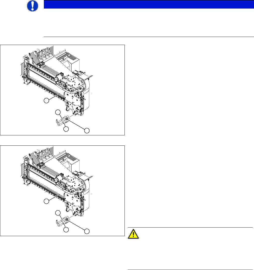
1. X axis reference point proximity switch
2. X axis end position proximity switch
3. End position proximity switch mount
4. Reference proximity switch strip
► Unplug the press-fit connections for the end position
proximity switch (2) or reference proximity switch (1)
from the gantry interface.
► Unthread the connection cable as far as the proximity
switches. You may need to remove the head adaptor
and the processor board.
► Loosen the screw fastening the proximity switch
mount (3).
1. X axis reference point proximity switch
2. X axis end position proximity switch
3. End position proximity switch mount
► Replace the relevant proximity switch and install the
proximity switch mount (3) with the proximity switch-
es.
► Make sure there is a gap of 0.4 mm between the prox-
imity switches and the trigger bar. Use the corre-
sponding thickness gauge (plastic).
► Reconnect to the electricity supply.
CAUTION!
Check how the cables are run!
Make sure that the axes can be moved without damaging
the cables.
Fasten the cables with cable ties.
2
3
1
4
2
3
1
4
Service Work
Gantries 3.3.3 Replacing the Y Axis Incremental Encoder [03090202-xx]
88 Service Manual SIPLACE X Series
3.3.3
3.3.3 Replacing the Y Axis Incremental Encoder [03090202-xx]
Replacing the Y Axis Incremental Encoder [03090202-xx]
Parts, equipment and tools
▪ Read head MS22.74 X/Y 950mm [03090202-xx] (replaces: [03003751-xx])
Removal/installation
NOTICE
Head interface
The new read head for the X axis "Read head MS22.74 X/Y 950 mm" [03090202-xx] may only
be fitted with a "head interface" from FS06 [03000901-06] or a "mirrored head interface" from
FS03 [03029048-03].
The read head can only be fitted together with a new " scale Siplace X-Series Y axis (1950
mm)" [03093792-xx]. If an old read head is upgraded to the new version MS22, you will also
need to replace the scale.
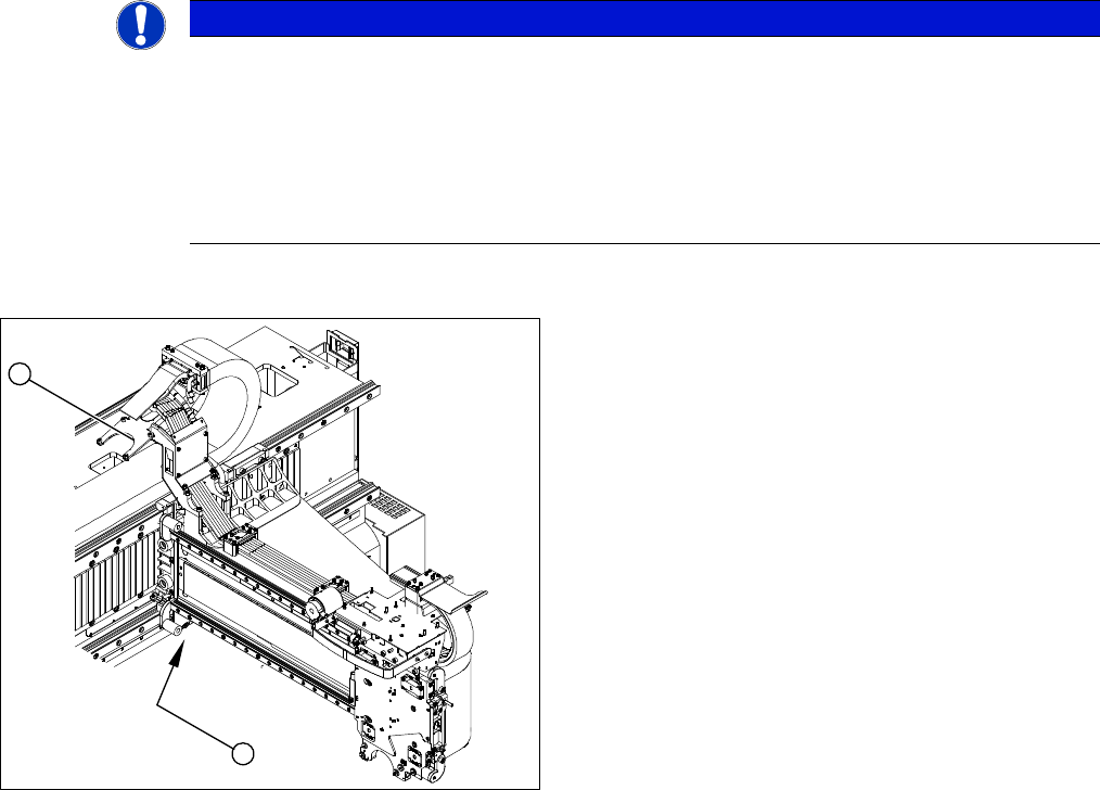
1. Position of the Y axis incremental encoder
2. Installation point for gantry interface
► Unplug the incremental encoder press-fit connection
from the gantry interface (2).
1
2