00194440-10_SM_X-Series_Customer_en.pdf - 第323页
Settings 5.4.2 Setting the Fixed Conveyor Edge (SW60x) Conveyor Settings Service Manual SIPLACE X Series 323 5.4.2.2 5 . 4 . 2 . 2 C o n v e y o r W id e n e d ( F o r S in g le C o n v e y o r M o d e ) Conveyor Widened…
Settings
Conveyor Settings 5.4.2 Setting the Fixed Conveyor Edge (SW60x)
322 Service Manual SIPLACE X Series
5.4.2
5.4.2 Setting the Fixed Conveyor Edge (SW60x)
Setting the Fixed Conveyor Edge (SW60x)
5.4.2.1
5.4.2.1 General Notes
General Notes
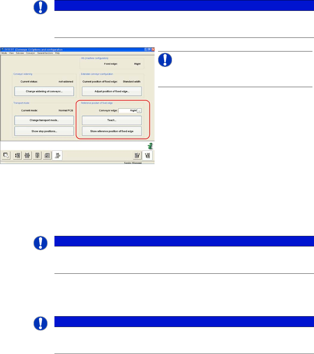
▪ The fixed conveyor edge can be set in SITEST if required.
▪ If the position taught for the fixed conveyor edge is saved, these values will be used for the function
Move all conveyor edges to standard position.
The default values will be overwritten and will need to be retaught.
▪ If these dimensions are incorrectly set on the single or dual conveyor, the PCB reference corner may
be moved, leading to fiducial errors during placement.
Two requirements for changing the fixed conveyor sides:
▪ Extra wide conveyor – moves the fixed conveyor side 34 mm outwards.
▪ Widened conveyor – moves the sides of the 2nd conveyor to the limit switch.
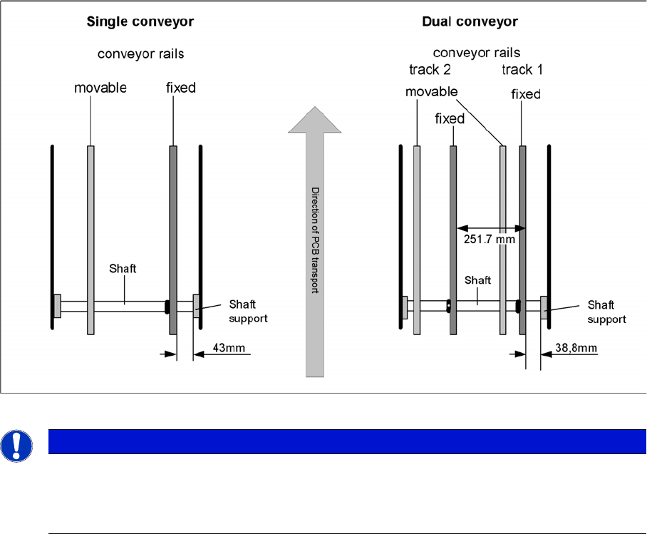
Single conveyor control mode (D-series up to 380 mm/HF, X lines up to 450 mm)
NOTICE
Widened or extra wide conveyor mode
If you want to change the conveyor mode from "widened" to "extra wide" (or vice versa), you
need to first move the conveyor into standard mode.
SITEST "Set fixed conveyor edge"
NOTICE!
This menu is protected with the SIPLACE service pass-
word.
NOTICE
SITEST
In the SR/MC station SW, the fixed conveyor edge of all lanes can be adjusted in the conveyor
firmware (flexible). However, this may only be set with the SITEST software.
NOTICE
D series
In the D series machines, you need to remove the clamping rings on the fixed conveyor edge
in advance.
Settings
5.4.2 Setting the Fixed Conveyor Edge (SW60x) Conveyor Settings
Service Manual SIPLACE X Series 323
5.4.2.2
5.4.2.2 Conveyor Widened (For Single Conveyor Mode)
Conveyor Widened (For Single Conveyor Mode)
► Go to the SITEST conveyor menu Options and Configurations and select Change widening of
conveyor to widen the conveyor.
► The conveyor sides for lane 2 (right side fixed (lane 1 left side fixed)) are moved to the limit switch.
No mechanical work is required for this.
► The SITEST SW ask for connecting the lifting tables.
⇨ Widening the PCB conveyor from it standard width allows you to accommodate boards up to
380 mm (for line combinations with X4/X3/X2 machines).
⇨ Widening the PCB conveyor from its "extra wide" width allows you to accommodate boards up to
450 mm (only for line combinations with HF and X machines).
Setting the "fixed conveyor side" in SIPLACE X, HF series
NOTICE
SITEST only
The fixed conveyor side should be adjusted only with the SITEST software and the width ad-
justment devices. This ensures that the conveyor sides are in their correct positions (parallel)
i.e. that the conveyor runs straight.
Settings
Conveyor Settings 5.4.2 Setting the Fixed Conveyor Edge (SW60x)
324 Service Manual SIPLACE X Series
Shaft fixtures (bearing flange)
See also
5.4.3.1.1 Setting the Fixed Conveyor Edge [ ➙ 326]
5.4.2.3
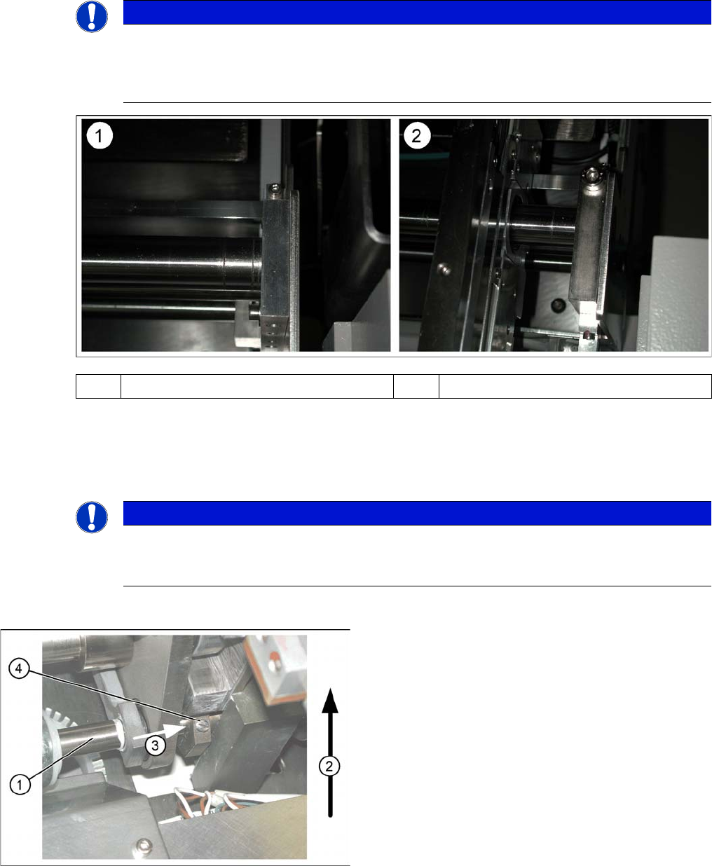
5.4.2.3 Connecting the Dual Conveyor Lifting Tables
Connecting the Dual Conveyor Lifting Tables
► Remove the lifting table plate on conveyor lane 2 in PA1 and on lane 1 in PA2.
► Loosen the lockscrew(s) (4) and use a screwdriver to push the hexagonal circlip over the shaft on
lifting table 1.
► Perform lifting table connection for all placement areas (arrangement rotated by 180°.)
NOTICE
Various versions
Since July 2007, X machines with single conveyors use a new version of the shaft fixtures
(bearing flange) with a width of 15 mm, instead of 12 mm. The setting for standard single con-
veyors changes with this new version, to 40 mm.
(1) Bearing flange – first version 12 mm (2) Bearing flange – new version 15 mm
NOTICE
Why is “Alternative Components” a topic for our customers?
This option is a mechanical necessity when you use the dual conveyor as a single conveyor.
The two lifting tables move parallel when they are connected.
Connecting lifting tables (e.g. PA1 conveyor lane 2
▪ The drive shaft (1) is connected to the piston rod of
the pneumatic cylinder. This shaft is connected with
the shaft of the lifting table from conveyor lane 1. The
lifting table drive shaft also has an additional rod with
a hexagonal circlip. This rod is pushed over the shaft
of lifting table 1.
▪ Direction of transport (2).
▪ Direction (3) in which the hollow shaft from lifting ta-
ble 2 (1 in PA 2) is to be moved to lifting table 1 (2 in
PA 2).
▪ Lock screws (4).