00194440-10_SM_X-Series_Customer_en.pdf - 第45页
Overview of the Modules 2.4.5 Width Adjustment X Series Component Changeover Table Service Manual SIPLACE X Series 45 2.13 2 . 1 3 X S e r ie s C o m p o n e n t C h a n g e o v e r T a b le X Series Component Changeover…
Overview of the Modules
HF R2 Docking Unit 2.4.5 Width Adjustment
44 Service Manual SIPLACE X Series
2.11
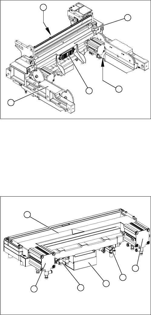
2.11 HF R2 Docking Unit
HF R2 Docking Unit
Overview
See also
3.8 COT Insert HF R2 [ ➙ 202]
2.12
2.12 Cutter
Cutter
Overview
See also
3.9 Cutter [ ➙ 210]
1. Component trolley feed device, complete
2. ODU connector with cable tree
3. Undocked short-stroke cylinder for the component
trolley
4. Control valves
5. Docked component trolley round cylinder
1
5
4
3
2
1. Tape cutter, pneumatic
2. Pneumatic cylinder
3. Control unit
4. Solenoid valves.
2
4
1
4
3
2
Overview of the Modules
2.4.5 Width Adjustment X Series Component Changeover Table
Service Manual SIPLACE X Series 45
2.13
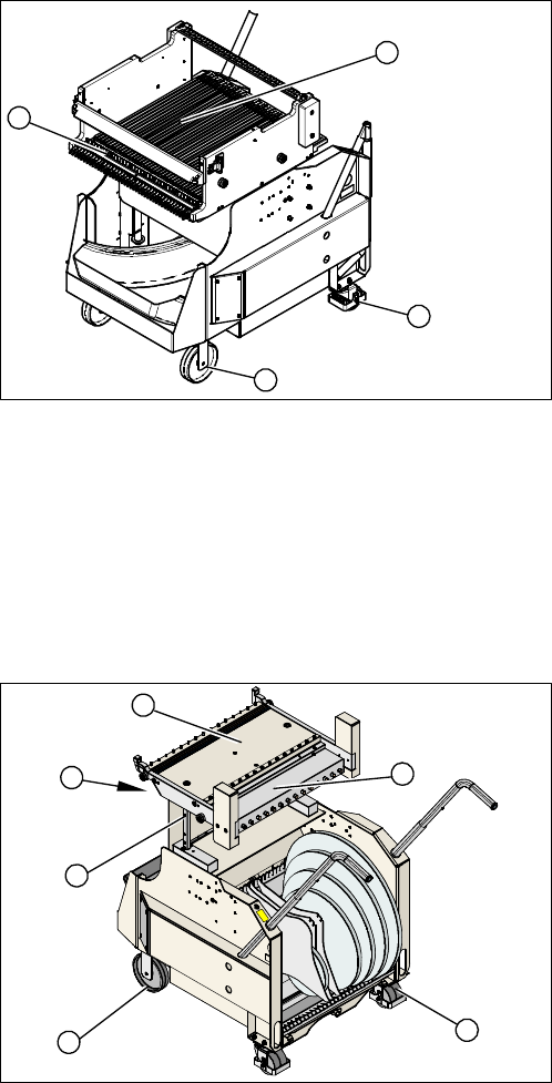
2.13 X Series Component Changeover Table
X Series Component Changeover Table
Overview
See also
3.10 X-Series Component Trolley [ ➙ 226]
2.14
2.14 HF R2 Component Changeover Table
HF R2 Component Changeover Table
Overview
See also
3.11 Component Trolley HF R2 [ ➙ 232]
1. Guide castor
2. Fixed castor
3. Locking strip
4. Support block
1
4
3
2
1. Table complete
2. Cable tree with ODU connector
3. Table plate
4. Feeder controller unit
5. Guide castors
6. Fixed castors
1
6
5
4
3
2
Overview of the Modules
Pneumatic Unit 2.4.5 Width Adjustment
46 Service Manual SIPLACE X Series
2.15
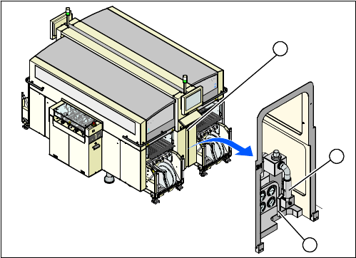
2.15 Pneumatic Unit
Pneumatic Unit
Overview
The pneumatic unit is mounted on a compact rack unit and is located in the right-hand middle section of
the machine. The unit is secured by a lockable door and contains the whole compressed air supply and
SMEMA interface (Siemens) to the series-connected stations.
See also
3.2.3.1 Pneumatic Unit - Version 1 [03004151-xx] [ ➙ 81]
3.2.3.2 Pneumatic Unit - Version 2 [03038058-xx] [ ➙ 82]
3.2.3.3 Pneumatic unit - version 3 [03060279-xx] [ ➙ 83]
1. Pneumatic unit
2. Coupling for compressed air connection
3. Shutoff valve
1
3
2