00194440-10_SM_X-Series_Customer_en.pdf - 第130页
Service Work Placement heads 3.4.2 Replacing the CPP Head 130 Service Manua l SIPLACE X Series 3.4.2.1 3 . 4 . 2 . 1 P r e p a r in g t h e H e a d f o r t h e I n s t a lla t io n H e ig h t Preparing the Head for the I…
Service Work
3.4.2 Replacing the CPP Head Placement heads
Service Manual SIPLACE X Series 129
► Carefully lift the head out of the locating pins on the head plate/from the hook.
Installation
► Follow the removal instructions in reverse order for installation. Also observe the following instruc-
tions:
See also
3.4.2.1 Preparing the Head for the Installation Height [ ➙ 130]
NOTICE
Additional work
► If you need to perform further work on this head (e.g. replacing spare parts), fit the head to
the head mount [03056231-xx].
CAUTION
Installation instructions
► Observe the correct installation height of the head! Read the service manual for your place-
ment head for more information.
► If you replace the head without the component camera, you will need to fit the old camera
onto the new head. Read the service manual for your placement head for more information.
► Make sure that the assembly position on the head plate is correct.
► Tighten the four fastening screws with a torque of 270 Ncm.
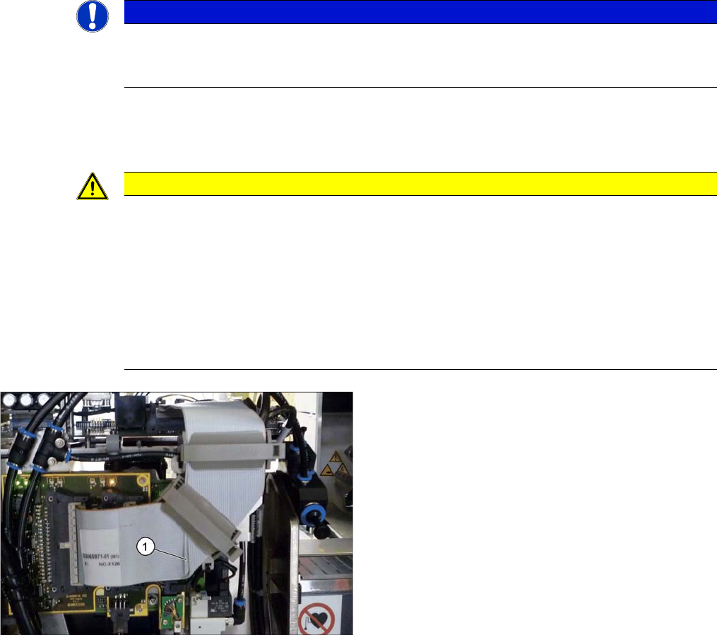
► Make sure that the flat ribbon cable is run correctly to the head adapter (see below).
Correct running of flat ribbon cable to head adapter
► Make sure that the flat ribbon cable is run correctly to
the head adapter. In particular, the cables must lie in-
side one another at the 90 degrees turn (1) and not
on top of one another, otherwise the connections on
the head adapter could be easily confused.
Service Work
Placement heads 3.4.2 Replacing the CPP Head
130 Service Manual SIPLACE X Series
3.4.2.1
3.4.2.1 Preparing the Head for the Installation Height
Preparing the Head for the Installation Height
Overview
CAUTION
Different heights
The placement head can be installed at two different heights. CPP_L corresponds to a compo-
nent height of six mm. CPP_H corresponds to a component height of 11.5 mm.
If the CPP head is used in a placement area with stationary camera, TwinHead or WPC, it may
only be used in the upper position.
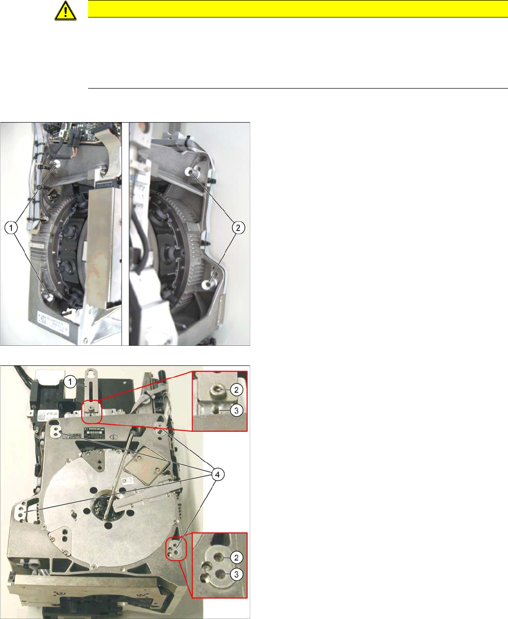
1. Fastening screws on the left side
2. Fastening screws on the right side
This diagram shows the fastening screws in the "head at
top" position.
1. Holding bracket
2. "Head at bottom" position
3. "Head at top" position
4. Fixture holes with bushings
Service Work
3.4.3 Replacing the Twin Head [03001095Sxx] Placement heads
Service Manual SIPLACE X Series 131
Conversion to another installation height
3.4.3
3.4.3 Replacing the Twin Head [03001095Sxx]
Replacing the Twin Head [03001095Sxx]
The TwinHead consists of two identical Twin segments, which are fitted at an angle of 180° to one an-
other.
Removal/installation
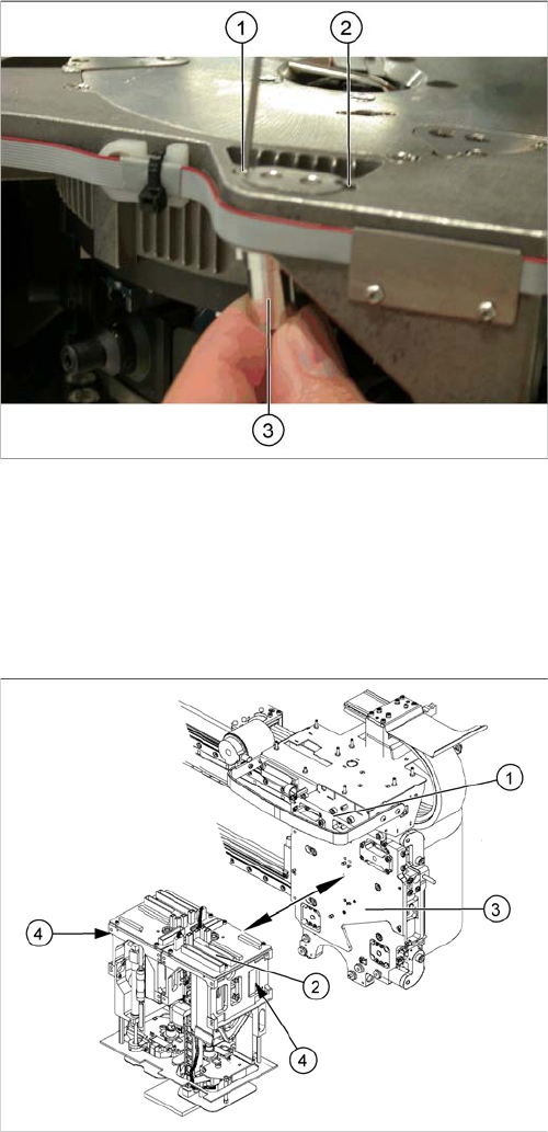
1. Drilling for the fastening screw of the bushing in "head
at bottom" position
2. Drilling for the fastening screw of the bushing in "head
at top" position
3. Bushing
All four bushings and the holding bracket must either be
fixed in top or bottom position.
Proceed as follows when replacing the bushings:
► Undo the fastening screws of the bushings.
► Insert the bushings in the correct position and re-
tighten them.
► Perform these steps for all four fastening bushings
and the holding bracket of the head.
► Move the component trolley out of the machine.
► Move the TwinHead into a position which allows you
best access.
► Loosen the pneumatic connection from the Twin-
Head vacuum generator to the pneumatic
distributor (1).
► Disconnect the exhaust air silicone hose from the
TwinHead vacuum generator (4).
► Unplug the pneumatic connection from the pneumat-
ic distributor (1) to the TwinHead return cylinder.
► Unplug the flat ribbon cable from the head main
board (2) on the TwinHead.
Each module is fixed with four screws to the head
plate (3) and is positioned with two pins.