00194440-10_SM_X-Series_Customer_en.pdf - 第25页
Overview of the Modules 2.2.1 Axis Units Electrical System Service Manual SIPLACE X Series 25 2.2.1 2 . 2 . 1 A x is U n it s Axis Units 2.2.1.1 2 . 2 . 1 . 1 A x is C o n t r o lle r Axis Controller View and test signal…
Overview of the Modules
Serial Number of Module
24 Service Manual SIPLACE X Series
2.1
2.1 Serial Number of Module
Serial Number of Module
2.2
2.2 Electrical System
Electrical System
Overview
See also
3.1 Electrics and Control [ ➙ 49]
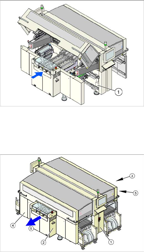
The serial number of your placement machine can be
found on the typeplate. This is located on the inside of lo-
cation 1, at the side (1).
Overview (example of X2 shown)
1. Power supply
2. Axis unit
3. Computer unit
4. Main distributor (sector 2)
5. Subdistributor (sector 4)
6. Transport direction
Overview of the Modules
2.2.1 Axis Units Electrical System
Service Manual SIPLACE X Series 25
2.2.1
2.2.1 Axis Units
Axis Units
2.2.1.1
2.2.1.1 Axis Controller
Axis Controller
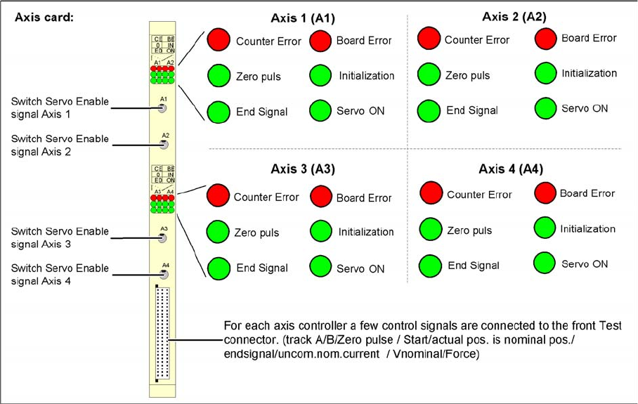
View and test signals for A364 axis controller of SIPLACE machine
The target position and start signal from the MC are transmitted to the axis controllers, which perform all
necessary calculations and controls.
The axis controller A364 in the SIPLACE machine is slot-coded. This means that no address switch
needs to be set when spare parts are replaced.
The communication and axis control functions are performed by the axis controller.
The corresponding BIOS SW and applications 1 and 2 are responsible for this.
The various drive types (motors) make different entries necessary in the control parameters. This leads
to different firmware versions for the axis types.

Overview of the Modules
Electrical System 2.2.1 Axis Units
26 Service Manual SIPLACE X Series
2.2.1.2
2.2.1.2 A363 - Axis Cards for X Machine Types and Head Modularity
A363 - Axis Cards for X Machine Types and Head Modularity
X4 Assembly 1 Adr. Assembly 2 Adr. Assembly 3 Adr. Assembly
4
Adr.
Placement area 1 Gantry 1 Gantry 4
Axis type/gantry X1 0 Z1_1 3 X4 6 Z4_1 9
Axis type/gantry Y1 1 DP1_1 4 Y4 7 DP4_1 10
Axis type/gantry S1
Z1_2
2Free
DP1_2
5S4
Z4_2
8Free
DP4_2
11
Placement area 2 Gantry 2 Gantry 3
Axis type/gantry X2 16 Z2_1 19 X3 22 Z3_1 25
Axis type/gantry Y2 17 DP2_1 20 Y3 23 DP3_1 26
Axis type/gantry S2
Z2_2
18 Free
DP2_2
21 S3
Z3_2
24 Free
DP3_2
27
X3 Assembly 1 Adr. Assembly 2 Adr. Assembly 3 Adr. Assembly
4
Adr.
Placement area 1 Gantry 1 Gantry 4
Axis type/gantry X1 0 Z1_1 3 X4 6 Z4_1 9
Axis type/gantry Y1 1 DP1_1 4 Y4 7 DP4_1 10
Axis type/gantry S1 2 Free 5 S4 8 Free 11
Placement area 2 Gantry 3
Axis type/gantry X3 22 Z3_1 25
Axis type/gantry Y3 23 DP3_1 26
Axis type/gantry S3
Z3_2
24 Free
DP3_2
27
X2 Assembly 1 Adr. Assembly 2 Adr. Assembly 3 Adr. Assembly
4
Adr.
Gantry 1 Gantry 2
Axis type/gantry X1 0 Z1_1 3 X2 6 Z2_1 9
Axis type/gantry Y1 1 DP1_1 4 Y2 7 DP2_1 10
Axis type/gantry S1
Z1_2
2Free
DP1_2
5S2
Z2_2
8Free
DP2_2
11