00194440-10_SM_X-Series_Customer_en.pdf - 第145页
Service Work 3.5.4 Replacing the Microswitch [03019563-xx] C&P20 Nozzle Changer Service Manual SIPLACE X Series 145 3.5.4 3 . 5 . 4 R e p la c in g t h e M ic r o s w it c h [ 0 3 0 1 9 5 6 3 - x x ] Replacing the Mi…
Service Work
C&P20 Nozzle Changer 3.5.2 Replacing the Board for the 1 Wire NC [03015388-xx]
144 Service Manual SIPLACE X Series
3.5.2
3.5.2 Replacing the Board for the 1 Wire NC [03015388-xx]
Replacing the Board for the 1 Wire NC [03015388-xx]
Removal/installation
3.5.3
3.5.3 Replacing the Complete Valve [03016830-xx]
Replacing the Complete Valve [03016830-xx]
Removal/Installation
NOTICE
New version [03015388-xx] is backwards compatible
Compared to the older version [03045735-xx], the new board is only equipped with an addition-
al interface for the CAN node assembly [03052927-01].
1. 1 wire board
2. 3 x fastening screws
► Label all connectors and leads connected to the 1
wire board (1).
► Unplug all connectors and leads from the 1 wire
board (1).
► Loosen the three screws (2) fastening the 1 wire
board (1).
► Install the new 1 wire board (1) and reconnect all
electrical leads.
► Fasten loose leads with cable ties.
2
1
2
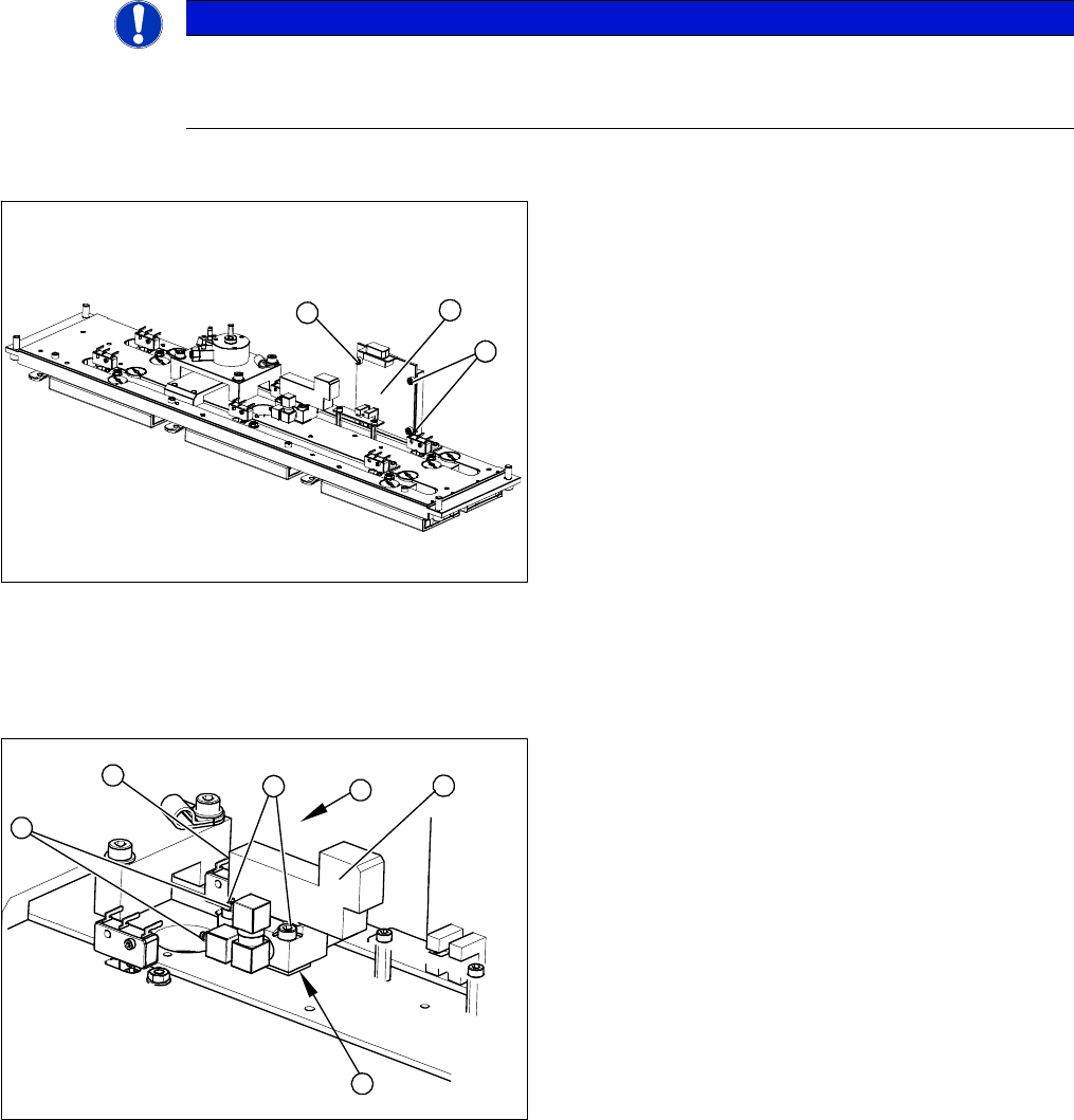
1. Valve assembly
2. 2 x fastening screws
3. 3 compressed air connections
4. Electrical connection
► Unplug the three compressed air connections (3)
from the valve.
► Disconnect from the power supply (4).
► Loosen the two fastening screws (2).
► Remove the valve (1).
⇨ Take care not to lose the shim (5). This needs to
be replaced in the correct position again, during
assembly.
► Install the valve (1) and reconnect the power (4) and
compressed (3) air supplies.
► Attach the cover and return the nozzle changer to the
machine.
4
3
3
5
1
2
Service Work
3.5.4 Replacing the Microswitch [03019563-xx] C&P20 Nozzle Changer
Service Manual SIPLACE X Series 145
3.5.4
3.5.4 Replacing the Microswitch [03019563-xx]
Replacing the Microswitch [03019563-xx]
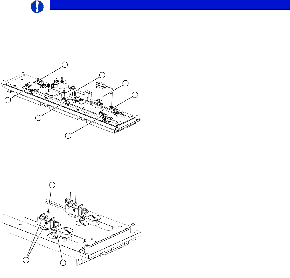
Overview
Removal/Installation
Adjusting the microswitch switching point
▪ Setting gauge [03028340-xx]
NOTICE
All microswitches are soldered into place.
You therefore need to unsolder the individual microswitches. You also need heat-shrinkable
sleeves, to pull over the contacts.
1-6: Microswitches for monitoring the nozzle magazine
(open/closed)
7: 1 wire board
6
5
4
7
1
3
2
1. Two fastening screws
2. Electrical connections
3. Fixing bracket
► Unsolder the electrical connections (2) at the relevant
microswitch.
► Loosen the two screws (1) fastening the microswitch.
► Install the new microswitch on the fixture bracket (3).
► Pull the heat-shrinkable sleeves over the electrical
connections and solder the connections.
► Warm the heat-shrinkable sleeves and make sure
that these cover the contacts tightly.
1
3
2
Service Work
C&P20 Nozzle Changer 3.5.5 Replacing the Three mm Green LEDs [03021168-xx]
146 Service Manual SIPLACE X Series
3.5.5
3.5.5 Replacing the Three mm Green LEDs [03021168-xx]
Replacing the Three mm Green LEDs [03021168-xx]
Removal/installation
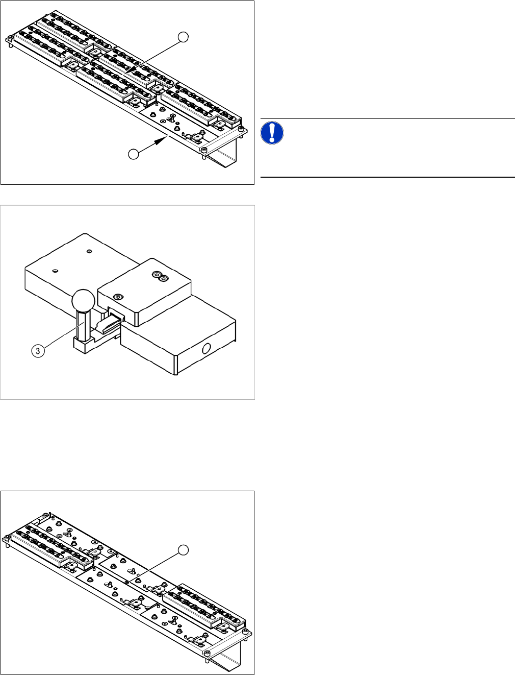
1. C&P20 nozzle changer with a free slot for setting
gauge [03028340-xx]
2. Green diode: shines when status is Nozzle changer
closed.
► Instead of the magazine (for which the microswitches
monitor the positions open/closed), attach the setting
gauge to the free nozzle changer slot (1).
NOTICE!
Make sure that all other nozzle changers are attached to
the nozzle changer!
Setting gauge for C&P20 nozzle changer [03028340-xx]
► Press in the lever (3) of the setting gauge. This sim-
ulates a closed magazine.
► Turn the nozzle changer over and carefully place it
down on the installation location, with the magazines
pointing downwards.
► Make sure you do not touch any electrical connec-
tions.
► Switch the machine on.
► Use the two fastening screws to adjust the micros-
witch, so that the green LED (2) shines.
⇨ This ensures that the microswitch switches cor-
rectly.
► Pull out the lever (3) of the setting gauge. This simu-
lates an open magazine.
⇨ Make sure that the green LED (2) does not shine!
1
2
1. Green LED three mm
► Remove the nozzle magazine in the center. The LED
is located beneath (1).
► Remove the cover (2).
► Pull the LED (1) out towards the back.
► Unplug the connection cable.
► Remove the cable ties.
1