00194440-10_SM_X-Series_Customer_en.pdf - 第64页
Service Work Electrics and Control 3.1.5 Replac ing the Axis Unit Assemblies [ 00353054-xx] 64 Service Manual SIPLACE X Series 3.1.5.2 3 . 1 . 5 . 2 O v e r v ie w o f A x is U n it ( w it h A 3 6 4 ) Overview of Axis Un…
Service Work
3.1.5 Replacing the Axis Unit Assemblies [00353054-xx] Electrics and Control
Service Manual SIPLACE X Series 63
3.1.5.1
3.1.5.1 Overview of Axis Unit (with A363) [00353054-xx]
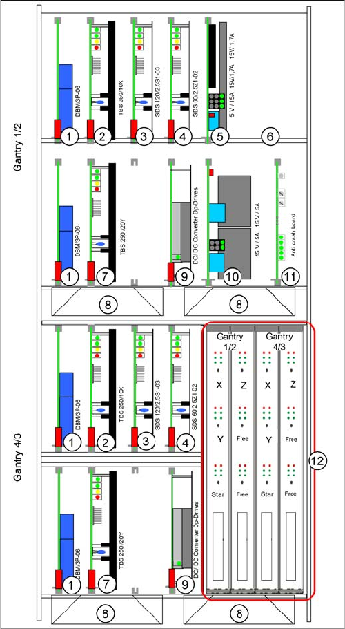
Overview of Axis Unit (with A363) [00353054-xx]
Axis unit with A363: configuration example C&P20 and
C&P20
The axis card A363 was fitted up to machine number B-
336.
The plug-in cards vary according to the machine configu-
ration. This example shows an axis unit with two C&P20
heads in placement area 1.
1. Brake board for each X axis and Y axis
2. Servo amplifier X axes
3. Star axis servo amplifier
4. Servo amplifier Z axis
5. Power supply +/- 15, +5 V
6. Ballast circuit (only in axis unit PA2)
7. Servo amplifier Y axes
8. Fan unit
9. DC/DC converter, DP drives
10. Power supply +/- 15V
11. Anti-crash board
12. Axis controller boards
Service Work
Electrics and Control 3.1.5 Replacing the Axis Unit Assemblies [00353054-xx]
64 Service Manual SIPLACE X Series
3.1.5.2
3.1.5.2 Overview of Axis Unit (with A364)
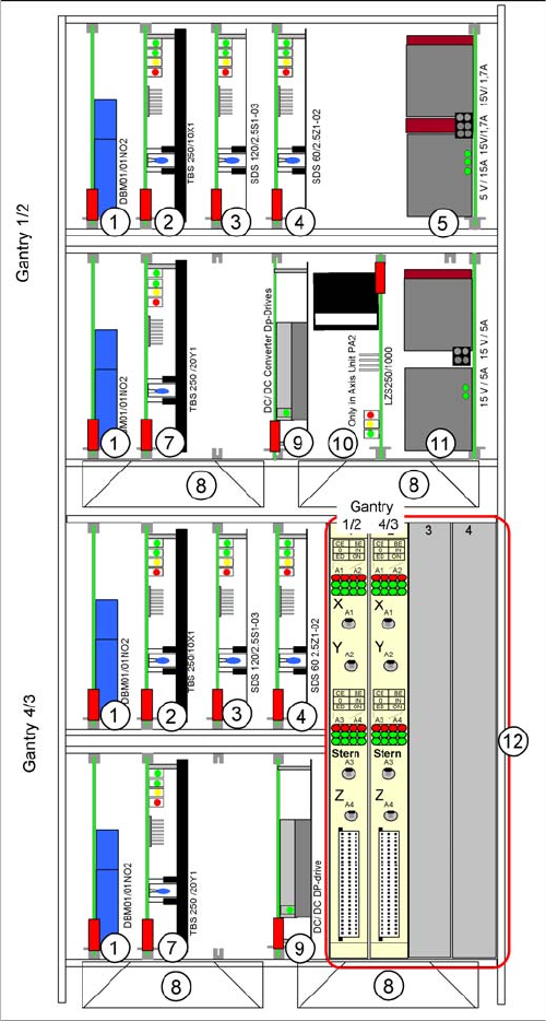
Overview of Axis Unit (with A364)
Axis unit with A364: configuration example C&P20 +
C&P20
From X-Series machine number B-337 and X4I onwards,
the axis card A364 [03041865-xx] has been fitted.
The anticrash board is no longer used as its function is in-
tegrated into the A364.
The plug-in cards can vary, according to the machine
configuration. This example shows an axis unit with two
C&P20 heads in placement area 2.
1. Brake board for each X axis and Y axis
2. Servo amplifier X axes
3. Star axis servo amplifier
4. Servo amplifier Z axis
5. Power supply +/- 15, +5 V
6. -
7. Servo amplifier Y axes
8. Fan unit
9. DC/DC converter, DP drives
10. Ballast circuit (only in axis unit PA2)
11. Power supply +/- 15V
12. Axis controller boards
Service Work
3.1.6 Replacing the Computer Unit Assemblies Electrics and Control
Service Manual SIPLACE X Series 65
3.1.6
3.1.6 Replacing the Computer Unit Assemblies
Replacing the Computer Unit Assemblies
3.1.6.1
3.1.6.1 Computer Unit [03002110-xx]
Computer Unit [03002110-xx]
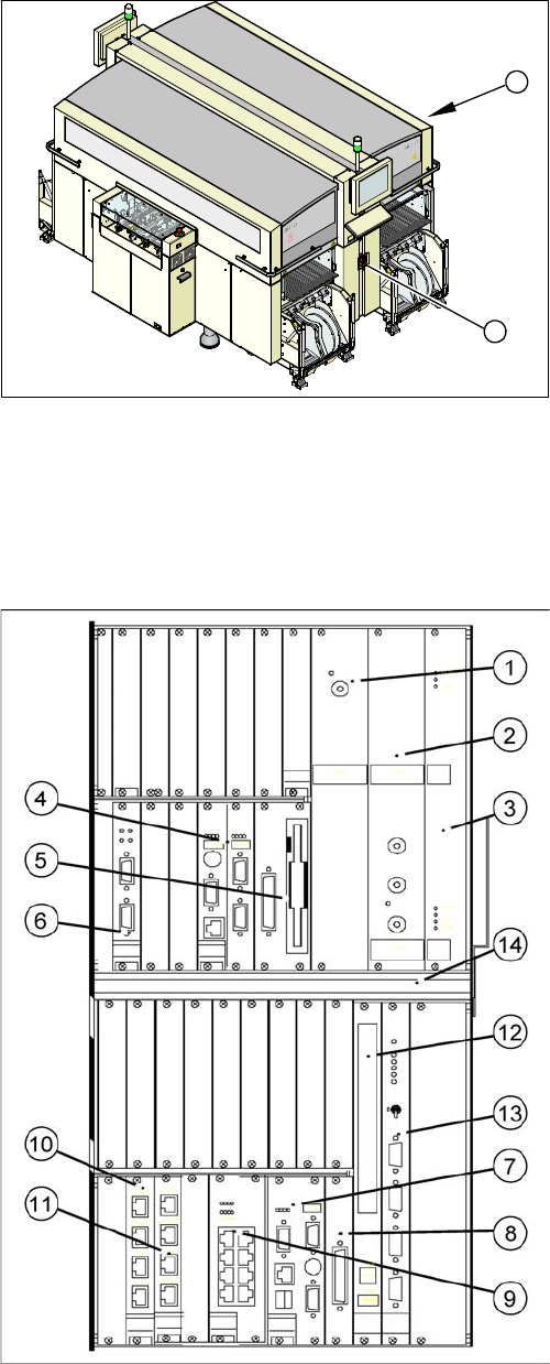
Overview
The backup battery 3.6 V is located at the back of the computer unit (on the outside of the rear panel
wiring board).
► End all placement operations on the machine.
► Switch the placement system off at the main switch
(1).
► Remove the cover on the computer unit (2).
⇨ If you wish to extract the computer unit, first re-
move the transportation locking screw.
1
2
Power supply / DC-DC converter
(1) Input +52 V / output +3.3 V, 20A
(2) Input +52 V / output +5.0 V, 60A
(3) Input +52 V / output +/- -12 V, 6A
Machine control (MC)
(4) CPU
(5) HD/FD drive
(6) CAN COM unit – connection above for PA1 / connec-
tion below for PA2
Control computer for station and Vision computer func-
tions (SR)
(7) CPU
(8) HD drive
(9) 2 x LAN interfaces for communication to the MC and
SIPLACE Pro computer
(10) 4 x hotlink interfaces for Vision functions /hotlink
card1: PA1
(11) 4 x hotlink interfaces for Vision functions /hotlink
card2: PA2
Other
(12) CD-ROM drive with USB connection
(13) Video multiplexer
(14) Fan unit