00194440-10_SM_X-Series_Customer_en.pdf - 第78页
Service Work Electrics and Control 3.1.11 Replac ing the Protective Cover Switch [03020409-XX] 78 Service Manual SIPLACE X Series 3.1.11 3 . 1 . 1 1 R e p la c in g t h e P r o t e c t iv e C o v e r S w it c h [ 0 3 0 2…

Service Work
3.1.10 LED Assignment on the Main Distributor Electrics and Control
Service Manual SIPLACE X Series 77
X7_8 Do7 nc
X8_1 Do8 nc
X8_2 Do9 nc
X8_3 Do10 nc
X8_4 Do11 nc
X8_5 Do12 St_GrüneLampe1/The right-hand green light from the fault indicator
shines if a "high" signal is present at the port output. Meaning: flashes
if no board is in the (right) conveyor lane.
X8_6 Do13 St_WeisseLampe1/The right-hand white light of the fault indicator lamp
shines if a "high" signal is present at the port output. Meaning: fault on
a feeder on location 1 or 2.
X8_7 Do14 St_WeisseLampe2/The left-hand white light of the fault indicator
shines if a "high" signal is present at the port output. Meaning: fault on
a feeder on location 3 or 4.
X8_8 Do15 St_GrüneLampe2/The left-hand green light from the fault indicator
shines if a "high" signal is present at the port output. Meaning: flashes
when no PCB in the (left) conveyor lane.
X9_1 24 V
X9_2 24 V
X9_3 24 V
X9_4 24 V
X9_5 GND
X9_6 GND
X9_7 GND
X9_8 GND
Terminals I / O Description / Note
Service Work
Electrics and Control 3.1.11 Replacing the Protective Cover Switch [03020409-XX]
78 Service Manual SIPLACE X Series
3.1.11
3.1.11 Replacing the Protective Cover Switch [03020409-XX]
Replacing the Protective Cover Switch [03020409-XX]
Overview
Removal/Installation
► Label the appropriate connections at the main or intermediate distributor.
► Unplug the connection cable.
► Unthread the connection cable as far as the cover switch. Where necessary, dismantle the covers.
► Loosen the screws fastening the cover switch.
► Fit the new cover switch.
► Rethread the connection cable and plug in the electrical connections.
► Close the protective cover and check that the cover switch engages properly and is actuated.
► Correct the position of the cover switch at the slots.
► Switch the machine on and check that the cover switch activates the safety circuit, when the protec-
tive cover is opened.
► Refit the covers.
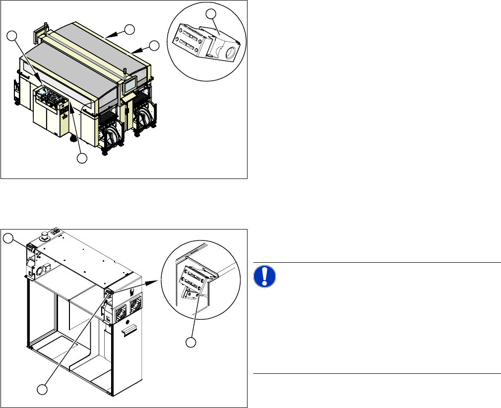
1. Installation position of cover switch at the input/output
side (when cover is open)
2. Cover switch with connection cable, complete
1
1
1
1
2
1. Cover switch
2. Fastening screws
NOTICE!
Connection cable for cover switch
The connection cables for the cover switch are either run
to the main or intermediate distributor, depending on the
location. Refer to the circuit diagram folders for the re-
spective machine.
Where necessary, dismantle the covers.
1
1
2
Service Work
3.1.12 Replacing the Servo Amplifier [00353446-xx] Electrics and Control
Service Manual SIPLACE X Series 79
3.1.12
3.1.12 Replacing the Servo Amplifier [00353446-xx]
Replacing the Servo Amplifier [00353446-xx]
▪ Servo amplifier Z axis TwinHead [00353446-xx]
▪ Servo amplifier DP axis TwinHead [00353447-xx]
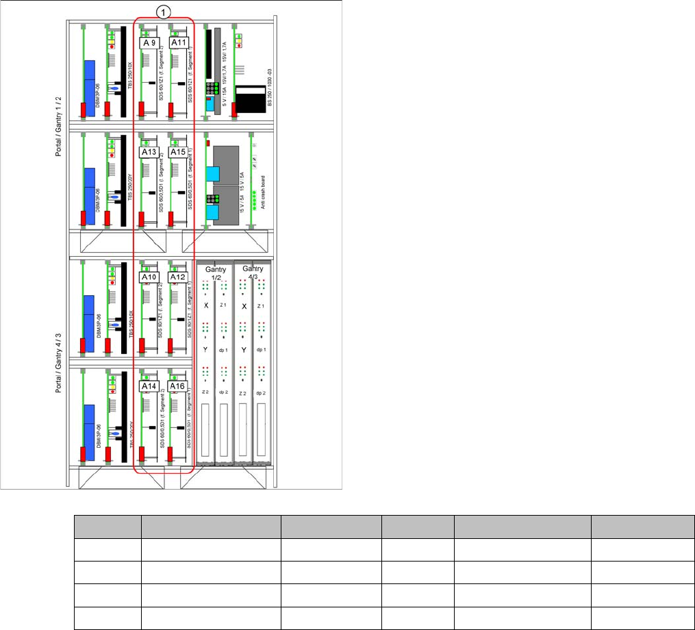
1. Slots for servo amplifier
Gantry 1 C&P head TwinHead gantry 2 C&P head TwinHead
A 9 Star axis Z-Axis A 10 Star axis Z-Axis
A 13 Not connected DP axis A 14 Not connected DP axis
A 11 Z-Axis Z-Axis A 12 Z-Axis Z-Axis
A 15 DP axis DP axis A 16 DP axis DP axis