00194440-10_SM_X-Series_Customer_en.pdf - 第346页
Settings Conveyor Settings 5.4.9 Checks After Mechanical Work on th e Conv eyor 346 Service Manua l SIPLACE X Series Troubleshooting See also 3.6.21 Rep lacing and Setting the Stopper (Q C) [030692 71-xx] [ ➙ 189] 5.…
Settings
5.4.8 Lifting Table Functions Conveyor Settings
Service Manual SIPLACE X Series 345
5.4.8.5
5.4.8.5 Adjusting the Clamping of the Lifting Table
Adjusting the Clamping of the Lifting Table
Parts, equipment and tools
▪ Setting gauge PCB clamping [00369202-xx]
Prerequisite
The lifting table must not be clamped.
Setting
The adjustment is performed in two steps:
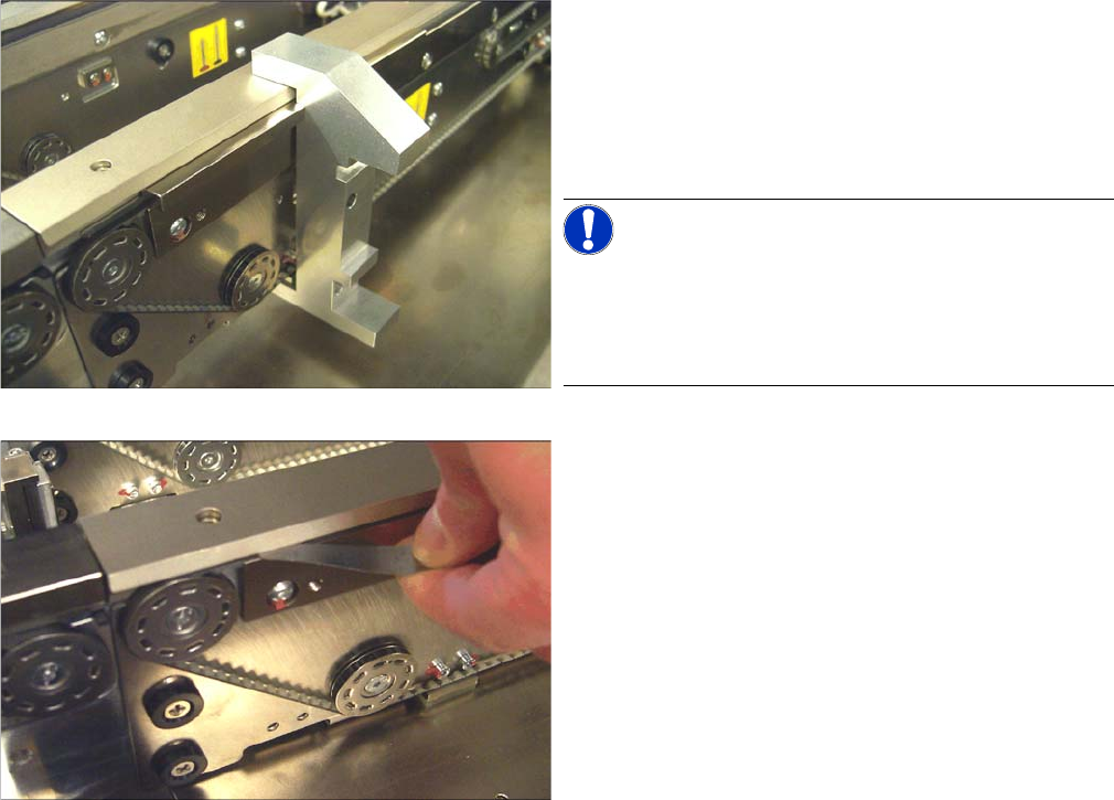
1. Preadjustment using the setting gauge
► Slide the setting gauge over the actuator.
► Check the position of the actuator. If the actuator is
not adjusted correctly, loosen its two fastening
screws and readjust it using the setting gauge.
Retighten the fastening screws in doing so.
NOTICE!
Quad lane
On Quad Lane conveyors the cabling of the stopper must
be opened for track 1L, 1R, 2L and 2R each. If necessary,
the stopper has to be removed completely.
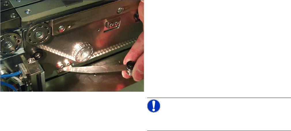
2. Checking the clamping
► Move the lifting table into the upper position without a
board.
► Check the clearance using a feeler gauge (0.1 mm).
For this purpose, move the feeler gauge coming from
the end of the belt (deflection pulley) between belt
and clamping edge.
⇨ If you notice a resistance, the clamping is adjusted
correctly.
⇨ If no resistance is noticeable on a clamped lifting
table and/or the clearance is greater than 0.1 mm,
this fact has to be compensated for at the actuator.
(See below)
► Perform this check on all four actuators of a track.
The clearance must not exceed 0.1 mm on any track.
Settings
Conveyor Settings 5.4.9 Checks After Mechanical Work on the Conveyor
346 Service Manual SIPLACE X Series
Troubleshooting
See also
3.6.21 Replacing and Setting the Stopper (QC) [03069271-xx] [ ➙ 189]
5.4.9
5.4.9 Checks After Mechanical Work on the Conveyor
Checks After Mechanical Work on the Conveyor
Check: The distance between the top edge of the conveyor belt and the top stop should be 6 mm.
Compensation of an overlarge clearance
If the clearance exceeds 0.1 mm at one point, this can be
compensated for at the actuator. For this purpose, per-
form the following steps:
► Determine the clearance between belt and clamping
edge. (e. g. 0.4 mm – This corresponds to a misad-
justment of 0.3 mm)
► Determine the distance between actuator and clam-
ing plate (see the picture). (e. g. 0.3 mm)
► Readjust the distance between actuator and clamp-
ing plate using the feeler gauge. (0.6 mm in the ex-
ample)
NOTICE!
Use feeler gauges or thin plates in the size of the actua-
tor.
► Clamp the lifting table and recheck the clearance on
all four actuators.
Settings
5.5.1 Setting the Actuator on the Component Trolley Settings on the Component Trolley
Service Manual SIPLACE X Series 347
5.5
5.5 Settings on the Component Trolley
Settings on the Component Trolley
5.5.1
5.5.1 Setting the Actuator on the Component Trolley
Setting the Actuator on the Component Trolley
Parts, equipment and tools
▪ Allen key
Setting
See also
3.10.6 Replacing the Actuator/Protective Bracket [ ➙ 231]
5.5.2
5.5.2 Component Trolley - Setting the Basic Height
Component Trolley - Setting the Basic Height
5.5.2.1
5.5.2.1 Parts, equipment and tools
Parts, equipment and tools
The following tools and equipment are needed to adjust the height of the component trolley:
▪ Set of Allen keys, size 5
▪ Eyebolt with M12 thread to raise the component trolley table,
DIN 580 M12-St [00048350-xx]
▪ Leverage device for raising the component trolley table, must be able to carry at least 80 kg
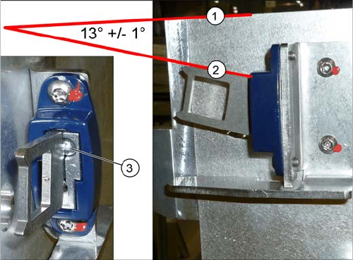
► Set the actuator with the help of the grub screw (3).
Between the upper edge (1) of the table and the
actuator (2) you need to set an angle of 13° +/- 1°.
The actuator must be able to slide into the safety
switch without rubbing against the plastic.