00194440-10_SM_X-Series_Customer_en.pdf - 第94页
Service Work Gantries 3.3.5 Replacing the Cooling Tubes for the Y Axis Motor Cooling System 94 Service Manual SIPLACE X Series Checking and assessing how the tubes are run (1) Good condition – the tube s are run along al…
Service Work
3.3.5 Replacing the Cooling Tubes for the Y Axis Motor Cooling System [03003704 -xx] Gantries
Service Manual SIPLACE X Series 93
► Use cable ties to fix the two tubes at the top.
► Push the two cooling tube fixtures (3) onto the tubes.
For easier fitting, you can apply a little grease (Molykote) to the spacer of the black cooling tube.
► Fit the two cooling tube fixtures (3) to position 5 (4) and 10 (5) in the trailing cable profile (6).
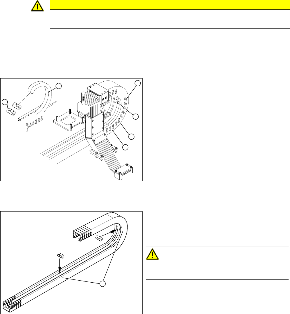
Installation of black and white cooling tubes
Observe the following for white cooling tubes!
CAUTION
Observe the preferred direction during installation!
► Observe the curvature (preferred direction) of the tube.
► Push the two cooling tube fixtures (1) onto the tubes
(2).
► Fit the two cooling tube fixtures (1) to position 5 (3)
and 10 (4) in the trailing cable profile (5) - from below.
► Note: For black cooling air tube only:
Carefully lubricate the cooling tubes with a small
amount of grease (Molykote).
► Push the gantry into the first end position (the long
part of the trailing cable is at the top).
► Check how the tubes are run in the trailing cable pro-
file. Make sure the tube is neither too short nor too
long - depending on the relevant travel range. The
following photos should help you to assess how well
the tubes have been run.
1
5
4
3
2
1
► Insert the two support rollers into the holes (1) provid-
ed in the power track chain.
► Push the gantry into the first end position (the long
part of the trailing cable is at the top).
CAUTION!
Do not lubricate white cooling tubes!
Do not apply grease to the white tubes.
► Check how the tubes are run in the trailing cable pro-
file. Make sure the tube is neither too short nor too
long - depending on the relevant travel range. The
following photos should help you to assess how well
the tubes have been run.
1
Service Work
Gantries 3.3.5 Replacing the Cooling Tubes for the Y Axis Motor Cooling System
94 Service Manual SIPLACE X Series
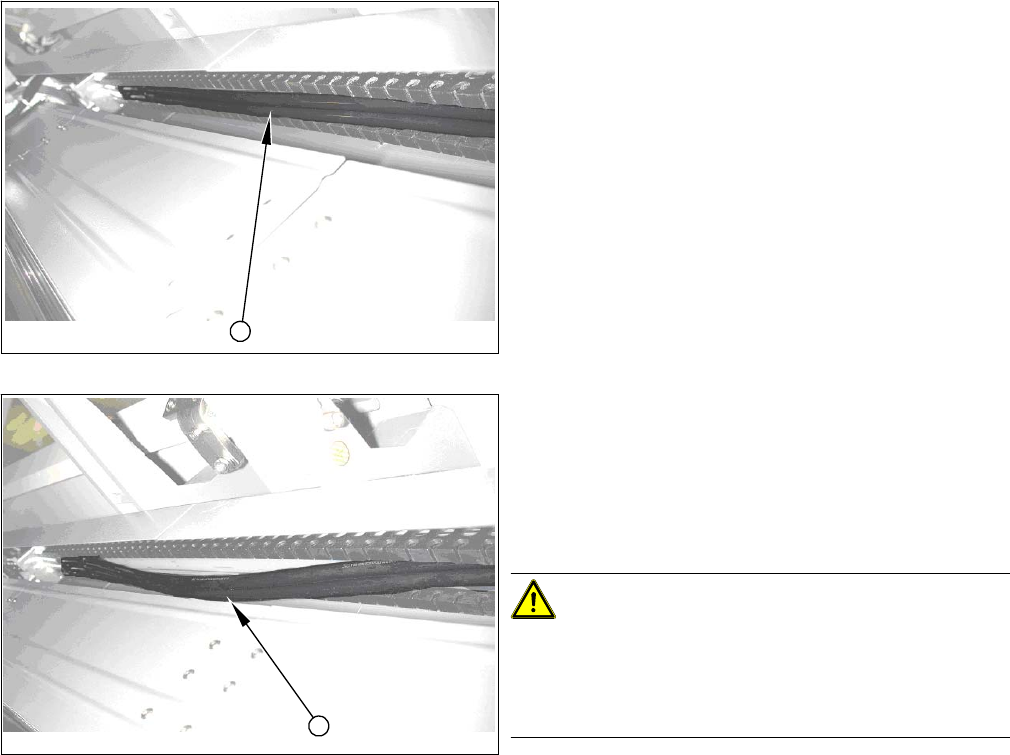
Checking and assessing how the tubes are run
(1) Good condition – the tubes are run along all positions
of the axes in the trailing cable profile.
► Move the gantry to the second end position and then
back again to the first end position. The long trailing
part will be at the bottom for the second end position
and at the top again for the first end position.
(2) Poor condition – the tubes are run in a slight loop .
► Shorten the tubes by approx. two to three mm.
► Move the gantry to the second end position and then
back again to the first end position. The long trailing
part will be at the bottom for the second end position
and at the top again for the first end position.
CAUTION!
Extract tubes carefully
If you need to extract the tube again, never pull it out of
the connection tubes with force (this could stretch the
tubes).
Gently lever the tube out with a screwdriver or similar
tool.
1
2
Service Work
3.3.6 Replacing the Head Plate Sensor [03013143-xx] Gantries
Service Manual SIPLACE X Series 95
3.3.6
3.3.6 Replacing the Head Plate Sensor [03013143-xx]
Replacing the Head Plate Sensor [03013143-xx]
Removal
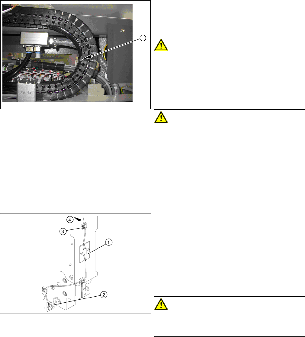
► Check how the tubes are run in the U profile.
The tube must not be stretched at fixture position 10 (1)
in any end position. Please refer to the photo on the left
for the maximum permissible tension.
CAUTION!
Observe the length and bending radius of the tube!
If the tube is shorter and the bending radius therefore
smaller, discard it and run a new tube.
► Run the tubes to the Y axis motor and connect it.
► Fix the tubes to the flange with cable ties.
CAUTION!
Ensure that the cooling tubes are firmly attached to the Y
motor and distributor and that they have been fixed with
cable ties.
If the cooling tubes loosen, the Y motor will not be cooled
properly.
1
1. Temperature sensor 1 (board)
2. Temperature sensor 2 (board)
3. Cable clamps
4. To the head interface
► Unplug the cable (4) at the head interface, unthread
it and release all cable clamps (3).
► Undo and remove the two screws fastening the first
board (1).
CAUTION!
There is another small board under this board. This does
not need to be replaced and must remain in the head
plate.
► Loosen the screw fastening the second board (2).