00194440-10_SM_X-Series_Customer_en.pdf - 第79页
Service Work 3.1.12 Replacing the Servo Amplifier [00353446-xx] Electrics and Control Service Manual SIPLACE X Series 79 3.1.12 3 . 1 . 1 2 R e p la c in g t h e S e r v o A m p lif ie r [ 0 0 3 5 3 4 4 6 - x x ] Replaci…
Service Work
Electrics and Control 3.1.11 Replacing the Protective Cover Switch [03020409-XX]
78 Service Manual SIPLACE X Series
3.1.11
3.1.11 Replacing the Protective Cover Switch [03020409-XX]
Replacing the Protective Cover Switch [03020409-XX]
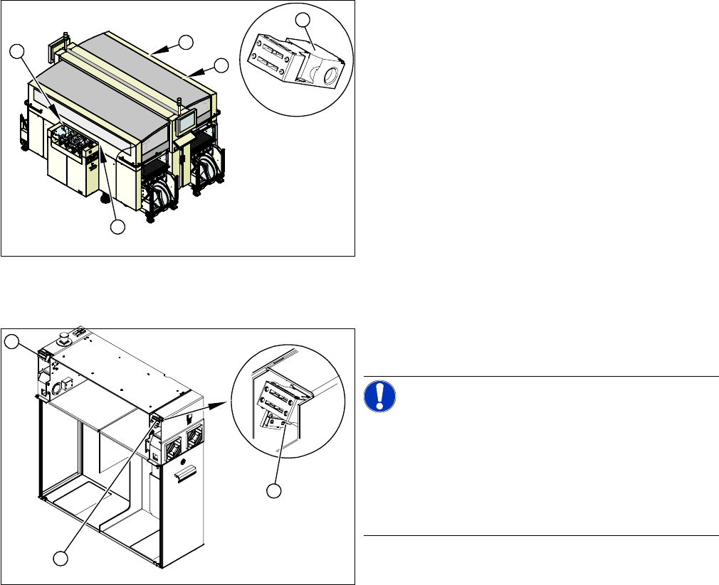
Overview
Removal/Installation
► Label the appropriate connections at the main or intermediate distributor.
► Unplug the connection cable.
► Unthread the connection cable as far as the cover switch. Where necessary, dismantle the covers.
► Loosen the screws fastening the cover switch.
► Fit the new cover switch.
► Rethread the connection cable and plug in the electrical connections.
► Close the protective cover and check that the cover switch engages properly and is actuated.
► Correct the position of the cover switch at the slots.
► Switch the machine on and check that the cover switch activates the safety circuit, when the protec-
tive cover is opened.
► Refit the covers.
1. Installation position of cover switch at the input/output
side (when cover is open)
2. Cover switch with connection cable, complete
1
1
1
1
2
1. Cover switch
2. Fastening screws
NOTICE!
Connection cable for cover switch
The connection cables for the cover switch are either run
to the main or intermediate distributor, depending on the
location. Refer to the circuit diagram folders for the re-
spective machine.
Where necessary, dismantle the covers.
1
1
2
Service Work
3.1.12 Replacing the Servo Amplifier [00353446-xx] Electrics and Control
Service Manual SIPLACE X Series 79
3.1.12
3.1.12 Replacing the Servo Amplifier [00353446-xx]
Replacing the Servo Amplifier [00353446-xx]
▪ Servo amplifier Z axis TwinHead [00353446-xx]
▪ Servo amplifier DP axis TwinHead [00353447-xx]
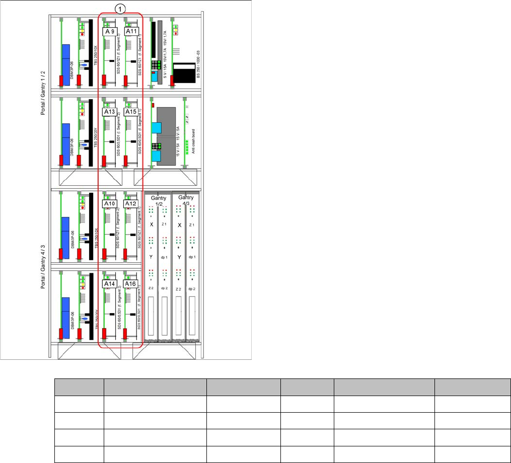
1. Slots for servo amplifier
Gantry 1 C&P head TwinHead gantry 2 C&P head TwinHead
A 9 Star axis Z-Axis A 10 Star axis Z-Axis
A 13 Not connected DP axis A 14 Not connected DP axis
A 11 Z-Axis Z-Axis A 12 Z-Axis Z-Axis
A 15 DP axis DP axis A 16 DP axis DP axis
Service Work
Pneumatic 3.2.1 Sealing the Screwed Connections
80 Service Manual SIPLACE X Series
3.2
3.2 Pneumatic
Pneumatic
Pneumat ic System - Using th e Correc t Blanking Plugs
3.2.1
3.2.1 Sealing the Screwed Connections
Sealing the Screwed Connections
3.2.2
3.2.2 Manometer for Pneumatic Unit
Manometer for Pneumatic Unit
CAUTION
Use the correct blanking plugs
► Only use blanking plugs in the machine which match the manufacturer's compressed air
connection. A tight fit cannot be guaranteed for other blanking plugs.
► We recommend the use of blanking plugs made by Festo.
NOTICE
Sealing the Screwed Connections
If compressed air screwed connections are loosened, these will need to be sealed again after-
wards. Always use the same sealing technique as was used before they were removed.
There are several different sealing techniques:
► Sealing ring (rubber or plastic)
These are either supplied or you can use the ones used before. Check the condition of the
sealing rings for damage.
► Sealant
There are several variants of this:
Loctite 567 [03097172-xx] and Loctite 55 [03092492-xx] – after loosening the connection,
clean the screwed thread and seal it with Loctite. The sealing thread for Loctite 55 must be
wound on in the direction of the screwed thread.
There may also already be a sealant on the screwed thread.
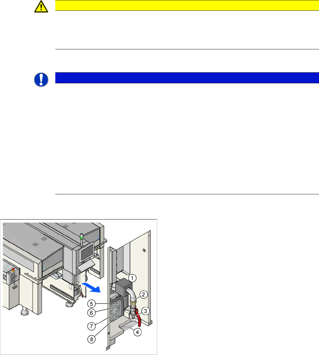
1. Pneumatic unit
2. Compressed air hose coupling
3. Shutoff valve
4. Gap for compressed air hose
5. Manometer for input pressure
6. Manometer for bulkcase or nozzle changer DLM
7. Manometer for gantries
8. Manometer for machine components (docking unit,
conveyor, cutter, NC C&P20)