00194440-10_SM_X-Series_Customer_en.pdf - 第339页
Settings 5.4.8 Lifting Table Functions Conveyor Settings Service Manual SIPLACE X Series 339 5.4.8 5 . 4 . 8 L if t in g T a b le F u n c t io n s Lifting Table Functions Lifting table up function Requirements for de tec…
Settings
Conveyor Settings 5.4.7 Readjusting the Holder for the Stopper and Proximity Switch (QC)
338 Service Manual SIPLACE X Series
5.4.7
5.4.7 Readjusting the Holder for the Stopper and Proximity Switch (QC)
Readjusting the Holder for the Stopper and Proximity Switch (QC)
If the fixture rail for the stopper and proximity switch is loosened or dismantled, this will need to be read-
justed.
Tools
▪ Standard tool
▪ Gauge for Stopper Setting [03067221-xx]
Performing the setting
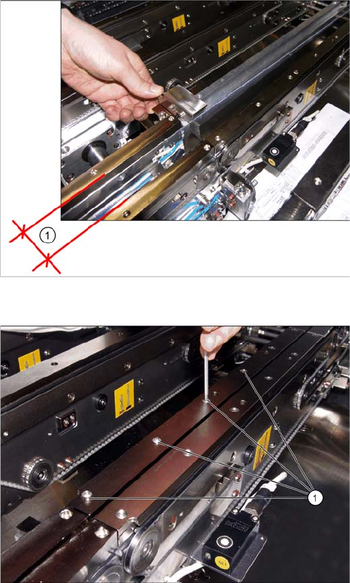
Position of the conveyor edges with setting gauge.
1. Distance between the conveyor edges for fitting the
setting gauge
► When dismantling the belt guidance, make sure that
the slide is secured.
► Set the conveyor so that the conveyor edges are not
against one another.
Dismantling the clamping and distance rail.
► Loosen the screws (1) and dismantle the clamping
rail and the distance rail of the conveyor edge.
Settings
5.4.8 Lifting Table Functions Conveyor Settings
Service Manual SIPLACE X Series 339
5.4.8
5.4.8 Lifting Table Functions
Lifting Table Functions
Lifting table up function
Requirements for detecting that the lifting table is up:
▪ 30-35 pulses from the incremental disc
▪ Check performed by software (see "5.4.6 Board Clamping Functions" [ ➙ 333])
▪ Dynamic response for board clamping of approx. 500 ms
Lifting table down function
Requirements for detecting that the lifting table is down:
▪ 30-35 pulses from the incremental disc
▪ Proximity switch on the lifting table cylinder
▪ Dynamic response for board release of approx. 480 ms
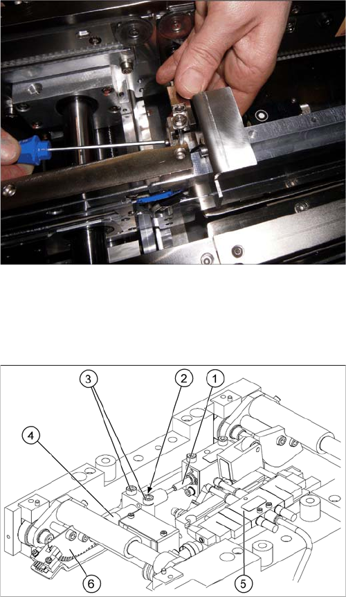
Fitting the stopper unit on the bracket with the help of the
setting gauge
► Position the gauge on the pins. Lift the holder and
align it to the setting gauge (in X direction and height).
► Then dismantle the setting gauge and fit the distance
and clamping rail.
Lifting table unit
1. Actuator
2. Lock nut damper
3. Fastening screws for mounting block
4. Damping unit
5. 3/5 way solenoid valve mounted on lifting table drive
cylinder
6. Fork-type light barriers / incremental disk
Settings
Conveyor Settings 5.4.8 Lifting Table Functions
340 Service Manual SIPLACE X Series
5.4.8.1
5.4.8.1 Adjusting the Speed of the Lifting Table (SW601)
Adjusting the Speed of the Lifting Table (SW601)
Applies for SW601. From SW 602 onwards, the lifting table speed can be checked in SITEST.
Parts
▪ Conveyor software [00322132-xx]
▪ Kvaser card
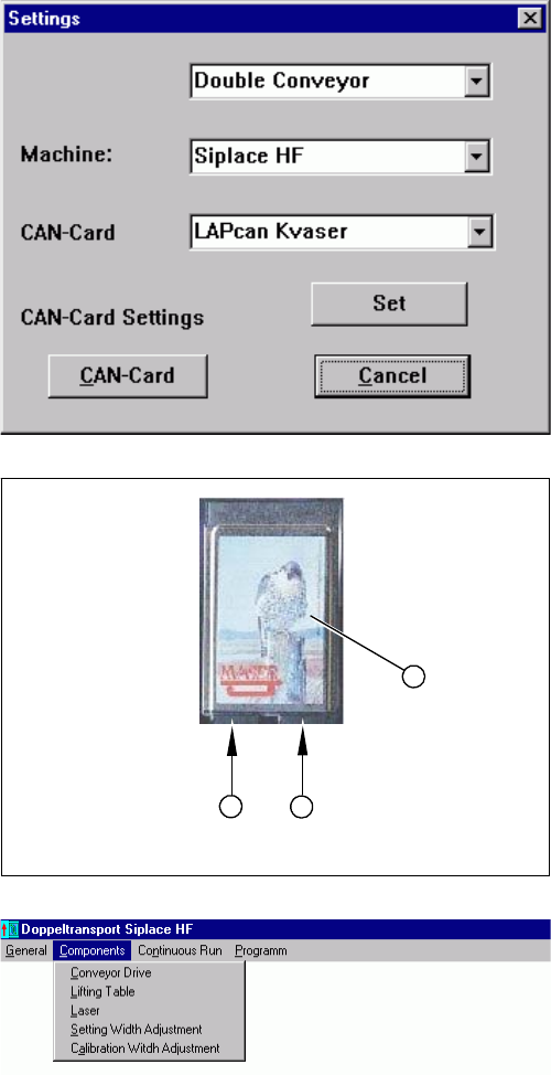
► Use the Kvaser card (1) to connect the service note-
book via the CAN Bus interface to the conveyor con-
trol.
► Start the conveyor software (LP_TSPMenu.exe).
► In the dialog box Settings, select the relevant convey-
or and machine type HF.
► Confirm your choice with Apply.
► Confirm the message Setting applied with OK.
1. Kvaser card
2. Channel 1
3. Channel 2
► Select the channel to be used with the Kvaser card:
channel 1 (2) or channel 2 (3).
► Confirm your setting with Apply.
► Confirm the message Setting applied with OK.
► In the Components menu, select the function Lifting
table. The Lifting table dialog box will open.
Prerequisite:
▪ That the machine is switched on
▪ That the safety covers are closed
▪ That the control unit is switched on
1
3
2