00194440-10_SM_X-Series_Customer_en.pdf - 第113页
Service Work 3.3.8 Replacing the Trailing Cable Gantries Service Manual SIPLACE X Series 113 ► Mark the pneumatic hoses through the holes (4) i n the gauge. Observe th e position labeled X hose . ► Use the hose pliers to…
Service Work
Gantries 3.3.8 Replacing the Trailing Cable
112 Service Manual SIPLACE X Series
Preparing the Trailing Cable
Handling and overview of gauge
The trailing cable is supplied as a complete assembly.
The pneumatic hoses need to be shortened to the exact length of the distance to the pneumatic distrib-
utor on the head mount and in the machine. Use the gauge to help you with this. The existing pneumatic
hoses, which are run in the machine, need to be cut through and connected to the trailing cable at the
exact position, with the help of hose couplings [03049770-01] provided.
There are two gauges available, for the different gantries.
▪ Gauge for trailing cable gantry 1+3 X-Series [00383029-01]
▪ Gauge for trailing cable gantry 2+4 X-Series [00383057-01]
▪ Only for the rotated gantry 2+4 for SIPLACE X4i:
Gauge for trailing cable SIPLACE X4i 2P G [03063762-01]
► Observe the designation for the respective gantry on the gauge (1) (gantry 1+3 or gantry 2+4). Se-
lect the correct gauge.
► Place the stopper edge (3) of the gauge (see mark labeled edge for clamp X+ Y on the gauge) at the
edge of the clamping plate (2) for the X trailing cable.
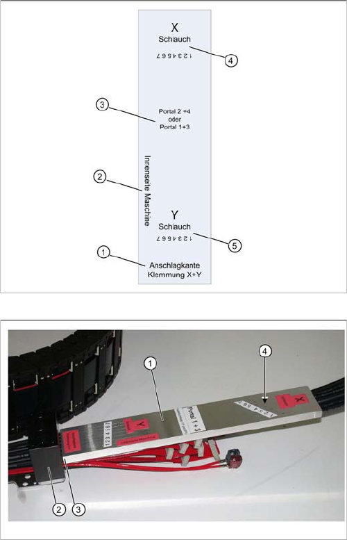
The gauges are labeled to ensure correct handling.
1. Stopper edge for clamp X and Y: this side of the
gauge must be attached to the respective trailing ca-
ble clamp.
2. Machine inside: this side of the gauge must point to
the inside of the machine.
3. Gauge designations
4. X hose: this is where you see the seven drillings for
the X hose markings.
5. Y hose: this is where you see the seven drillings for
the Y hose markings.
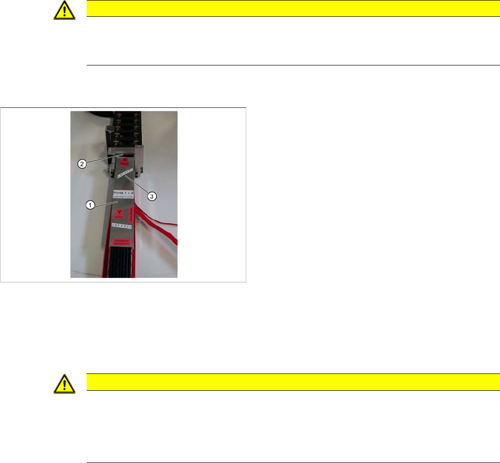
Shortening X hoses at the X trailing cable clamp (to the
pneumatic distributor at the head mount)
1. Gauge for shortening the hoses
2. X trailing cable clamp
3. Stopper edge (gauge at clamp)
4. Hose marking
Service Work
3.3.8 Replacing the Trailing Cable Gantries
Service Manual SIPLACE X Series 113
► Mark the pneumatic hoses through the holes (4) in the gauge. Observe the position labeled X hose.
► Use the hose pliers to cut the pneumatic hoses at the marked position. The pneumatic hoses can
now be run inside the pneumatic distributor, with the correct curvature.
► Observe the designation for the respective gantry on the gauge (1) (gantry 1+3 or gantry 2+4). Se-
lect the correct gauge.
► Place the stopper edge (2) of the gauge (see mark labeled edge for clamp X +Y on the gauge) at the
edge of the clamp for the Y axis.
► Mark the pneumatic hoses through the holes (3) in the gauge.
► Use the hose pliers to cut the pneumatic hoses at the marked position. The pneumatic hoses should
now have the correct length and can be connected to the severed pneumatic hoses in the machine
base.
CAUTION
Mark the correct position!
► Observe the position labeled X hose.
► Observe the position marked machine inside on the gauge.
Shortening the Y hoses to the pneumatic distributor in the
machine base
1. Gauge for shortening the hoses
2. Stopper edge at the machine base clamp
3. Hose marking
CAUTION
Mark the correct position!
► Observe the position labeled Y hose.
► To ensure that they have the correct length, cut the pneumatic hoses at the marking labeled
"Y hose". If the pneumatic hoses are cut too short, you will have to discard the entire trail-
ing cable.
Service Work
Gantries 3.3.8 Replacing the Trailing Cable
114 Service Manual SIPLACE X Series
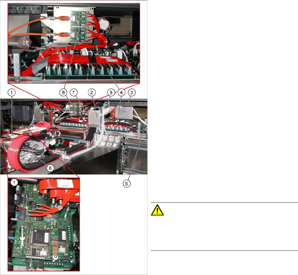
Overview
Version 1 from B-079
1. Head board with digital Vision board assembly
[03017836-xx]
2. Trailing cable console
3. Power track chain
4. Trailing unit interface gantry
5. Pneumatic hoses to the pneumatic distributor (in the
machine base)
6. Gantry distributor
7. Gantry Interface
8. Hotlink filter [03010670-xx]
9. Connection piece for cooling tubes to Y motor
► The flat ribbon cable and the camera cable are run
from the head board (1) via the trailing cable console
(2) and the power track chain (3) to the gantry inter-
face (7) and the trailing cable interface gantry (4).
The camera cable ends at the hotlink board (8).
► The pneumatic hoses are fed from the pneumatic dis-
tributor (6), via the trailing cable console (2) and the
power track chain (3) to the gantry distributor in the
machine base.
► Disconnect the camera cable from the hotlink board
(8).
► Remove cable ties where necessary.
CAUTION!
Note the order in which the terminal connections are ar-
ranged.
Label the press-fit connections to the flat ribbon cable
and the camera cable, for easier reconnection later.
► Disconnect the Y motor cooling tubes at the connec-
tion pieces (9).