00194440-10_SM_X-Series_Customer_en.pdf - 第247页
Measuring Equipment and Tools 4.1.1 Scope of Delivery SIPLA CE Diagnosis Adapter A364 [03051220 -0 1] Service Manual SIPLACE X Series 247 4.1.1 4 . 1 . 1 S c o p e o f D e liv e r y Scope of Delivery The SIPLACE ax is te…
Measuring Equipment and Tools
SIPLACE Axis Tester (SAT) [03002801-01]
246 Service Manual SIPLACE X Series
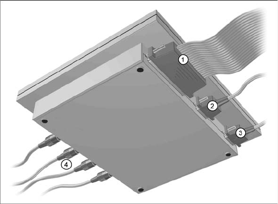
Axis tester - view from below
1. Connection for flat ribbon cable:
– At the axis tester end:
– 37-pin sub-d connector
– At the axis control end:
– 37-pin sub-d connector for the S-20/23/25/F4/F5 and HS-50 machines with the axis control
A361 or A362
– 25-pin sub-d connector for the S-15/F3, G machines and wafflepack changer with the axis con-
trol A360
An adapter is fitted to the flat ribbon cable to connect the 25-pin axis control. The operating volt-
ages of +5 V- ±5 % and ±15 V- ±5 % are fed via the 37 pin flat ribbon cable from the axis control
unit to the axis tester.
2. 9 pin Sub-D connector for CAN Bus cable e.g. for connection of CAN Bus controlled boards in the
machine – currently not used (transmission rate 128 kBaud to 1 MBaud, impedance 120 Ohm)
3. 9 pin Sub-D connector for the serial interface cable (V24) needed for software downloads, e.g. for
connection of an external PC (max. transmission rate up to 188 kBaud)
4. Four BNC sockets, connection impedance 50 Ohm. Socket assignment can be programmed. The
following signals can be assigned:
– Track signal A or B TTL level, max. 5 V
– Zero pulse TTL level tmin = 1 µsec
– End position signal TTL level tmin > 10 msec
– Trigger TTL level tmin > 10 msec
– Count error TTL level, trigger signal from count error sensor of oscilloscope
– Vtarget ±10 V, analog signal, Ri = 10 kOhm
– Force ±10 V analog signal, Ri = 10 kOhm
– VREG (resulting current) ±10 V analog signal, Ri = 10 kOhm
– Position deviation ±10 V analog signal; signal is generated internally, in the axis tester.
Measuring Equipment and Tools
4.1.1 Scope of Delivery SIPLACE Diagnosis Adapter A364 [03051220-01]
Service Manual SIPLACE X Series 247
4.1.1
4.1.1 Scope of Delivery
Scope of Delivery
The SIPLACE axis tester package [03002801-01] contains the following components:
▪ SIPLACE axis tester [03000761-01]
▪ Test cable A361 ... A363 (length 150 cm) with 37 pin connector and 37 pin socket for connection of
axis control units from S2x, F4/F5 and HS machines [03002803-01]
▪ CAN Bus cable [00349679-03]
▪ RS232-C cable [03002804-01]
▪ Manual for axis tester [00193370-01]
4.2
4.2 SIPLACE Diagnosis Adapter A364 [03051220-01]
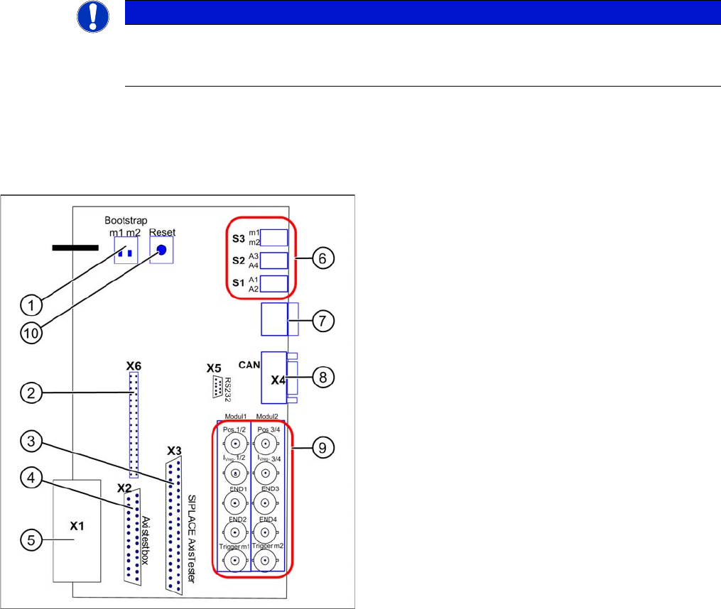
SIPLACE Diagnosis Adapter A364 [03051220-01]
Application:
This adapter card is used to check the A364 axis card dynamics.
The A364 axis card is equipped with two processors (module 1 and module 2) i.e. one processor controls
two axes.
NOTICE
A364, CAN test box
This adapter is designed for all machines with A364 and as an adapter for the CAN test box
with force measuring tool.
Adapter card for A364
Module 1: axis 1/2
Module 2: axis 3/4
1. Bootstrap mode: m1 = module1 / m2 = module2
2. Diagnosis – connector X6
3. Connection X3 SIPLACE AxisTester
4. Connection X2 Axis test box
5. Connection X1 to A364
6. Switches:
7. Diagnosis – 7 segment display
8. CAN bus connector (Sub-D)
9. BNC sockets:
10. Reset both processors
Measuring Equipment and Tools
Axis Tester (Old Version) and Adapter Board 4.1.1 Scope of Delivery
248 Service Manual SIPLACE X Series
4.3
4.3 Axis Tester (Old Version) and Adapter Board
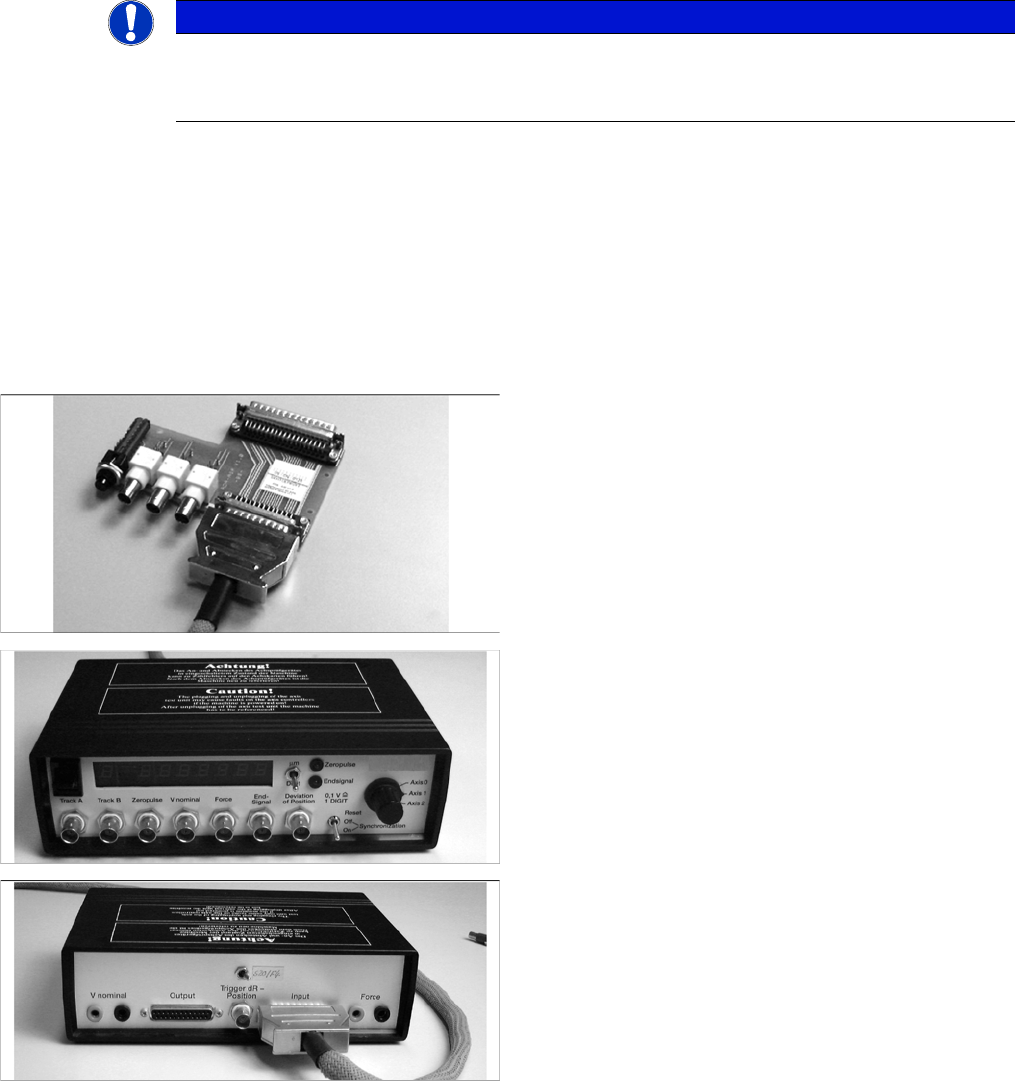
Axis Tester (Old Version) and Adapter Board
Article numbers
▪ Axis tester, inc. adapter board [00303430-06]
▪ Axis tester [00328041-05]
▪ Cable [00304771-03]
▪ Adapter board for axis tester [00328040-01]
Application:
Comparison of axis dynamics for placement head and gantry axes.
NOTICE
A363, A364
This axis tester is designed for all machines with A363. This function is limited for machines
with A364.
Adapter board for axis tester
Item no. [00328040-01]
SIPLACE axis tester – front
Item no. [00328041-05]
SIPLACE axis tester – back
Item no. [00328041-05]