00194440-10_SM_X-Series_Customer_en.pdf - 第111页
Service Work 3.3.8 Replacing the Trailing Cable Gantries Service Manual SIPLACE X Series 111 3.3.8.7 3 . 3 . 8 . 7 R e p la c in g t h e T r a ilin g C a b le ( I G U S ) f o r D 3 / X 4 I / X S e r ie s f r o m B - 0 7 …
Service Work
Gantries 3.3.8 Replacing the Trailing Cable
110 Service Manual SIPLACE X Series
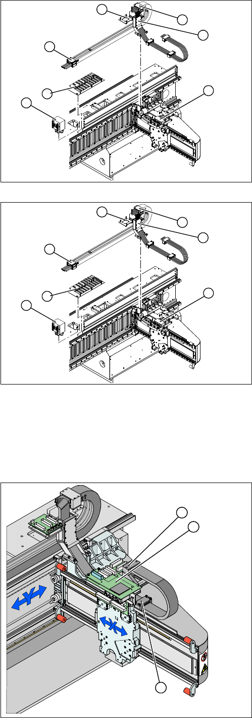
► Fit the gantry interface board onto the cable clamp (4)
of the new trailing cable.
► Loosely fasten the trailing cable console (1) with a
screw.
► Clean the trailing cable contact surface on the ma-
chine base with a dry cloth.
► Starting from the trailing cable console (1), run the flat
ribbon cable and hoses to the appropriate connec-
tions:
⇨ Pneumatic distributor (2)
⇨ Trailing unit interface gantry (3)
⇨ Gantry interface (4)
⇨ Gantry distributor (5)
► Reconnect to the electricity supply. Observe the cor-
rect connector assignment.
► Shorten the pneumatic hoses to the optimum length.
Make sure that they are not too long or too short.
They must engage firmly but should not buckle.
► Reconnect to the compressed air supply. Observe
the correct connector assignment.
► Loosely fasten the pressure plates (6) to the machine
base.
► Check that the power track chain can run along the
top of the machine base without obstruction. Move
the Y axis back and forth to check this.
► If necessary, correct at the trailing cable console (1)
and at the pressure plates.
► Fix the two pressure plates (6) and the trailing cable
console (1).Use Loctite 241 locking varnish to secure
them.
► Tighten the fastening screws for the trailing cable
console (1) crosswise.
► Reconnect the Y motor cooling tubes to the connec-
tion pieces.
► Fit the 3 pressure plates (1) at the gantry and head
mount (2).
►
Fit the head board (3). Make sure you do not lose the
contact disks or spacer bolts.
► Plug in all connections/terminals. Observe the cor-
rect connector assignment.
► Fasten new cable ties at the original points.
► Replace all dismantled cover plates in their original
positions.
2
5
4
6
6
1
3
2
5
4
6
6
1
3
5
1
3
2

Service Work
3.3.8 Replacing the Trailing Cable Gantries
Service Manual SIPLACE X Series 111
3.3.8.7
3.3.8.7 Replacing the Trailing Cable (IGUS) for D3/X4I/X Series from B-079 [03021065-xx]
Replacing the Trailing Cable (IGUS) for D3/X4I/X Series from B-079 [03021065-xx]
Introduction
Parts
▪ For SIPLACE X series machines with serial numbers from B-079 (version 1):
– Trailing cable, digital 1P - for placement area (PA) with 1 gantry: [03022236S01]
– Trailing cable, digital 2P U - for PA with 2 gantries, gantry 3 or 1: [03022237S01]
– Trailing cable, digital 2P G - for PA with 2 gantries, gantry 2 or 4: [03021065S01]
▪ For SIPLACE X series machines with serial numbers after B-079 (version 2):
– Trailing cable, digital 1P - for placement area (PA) with 1 gantry: [03050655Sxx]
– Trailing cable, digital 2P U - for PA with 2 gantries, gantry 3 or 1: [03050817Sxx]
– Trailing cable, digital 2P G - for PA with 2 gantries, gantry 2 or 4: [03050934Sxx]
▪ For SIPLACE X4I machines:
– Trailing cable, digital 2P U - for PA with 2 gantries, gantry 3 or 1: [03050817Sxx]
– Trailing cable SIPLACE X4i 2P G - for PA [03051596-xx], gantry 2 or 4: [03051596Sxx]
▪ Hose pliers for cutting the pneumatic hose
▪ Hose unlocking tool [03047090-xx]
▪ Pipe/hose cutters [00381443-01]
▪ Retrofitting guide for vacuum pump - if required - [00195089-01]:
▪ Locking varnish Loctite 241 [02101037-01]
The following auxiliary tools are included with trailing cable which have an S number:
▪ Gauge for trailing cable gantry 1+3 X-Series [00383029-01]
▪ Gauge for trailing cable gantry 2+4 X-Series [00383057-01]
▪ Scale for trailing cable X4I [00383057-xx]
▪ Edding marker, white [00382740-01]
▪ Press-fit connection QS-6 [03049770-01]
Preparation
In accordance with your machine's configuration, you will need to remove the relevant modules, covers
and cover plates before you can dismantle the trailing cable.
► Where necessary, remove the cover plates from the gantry trailing cable. Mark their exact position
to ensure correct replacement later.
► Remove the top central cover from the SIPLACE machine.
► Remove the upright covers over the trailing interface gantry, so that you can reach the trailing cable.
NOTICE
Old and new trailing cables
If the old trailing cable is replaced with a new trailing cable version, you will also need to replace
the hotlink card and the Vision board spread spectrum. These are not included in the spare
parts sets and need to be ordered separately!
The new trailing cable is installed after machine serial number B79 as version 2.
Service Work
Gantries 3.3.8 Replacing the Trailing Cable
112 Service Manual SIPLACE X Series
Preparing the Trailing Cable
Handling and overview of gauge
The trailing cable is supplied as a complete assembly.
The pneumatic hoses need to be shortened to the exact length of the distance to the pneumatic distrib-
utor on the head mount and in the machine. Use the gauge to help you with this. The existing pneumatic
hoses, which are run in the machine, need to be cut through and connected to the trailing cable at the
exact position, with the help of hose couplings [03049770-01] provided.
There are two gauges available, for the different gantries.
▪ Gauge for trailing cable gantry 1+3 X-Series [00383029-01]
▪ Gauge for trailing cable gantry 2+4 X-Series [00383057-01]
▪ Only for the rotated gantry 2+4 for SIPLACE X4i:
Gauge for trailing cable SIPLACE X4i 2P G [03063762-01]
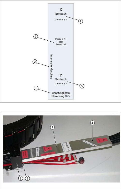
► Observe the designation for the respective gantry on the gauge (1) (gantry 1+3 or gantry 2+4). Se-
lect the correct gauge.
► Place the stopper edge (3) of the gauge (see mark labeled edge for clamp X+ Y on the gauge) at the
edge of the clamping plate (2) for the X trailing cable.
The gauges are labeled to ensure correct handling.
1. Stopper edge for clamp X and Y: this side of the
gauge must be attached to the respective trailing ca-
ble clamp.
2. Machine inside: this side of the gauge must point to
the inside of the machine.
3. Gauge designations
4. X hose: this is where you see the seven drillings for
the X hose markings.
5. Y hose: this is where you see the seven drillings for
the Y hose markings.
Shortening X hoses at the X trailing cable clamp (to the
pneumatic distributor at the head mount)
1. Gauge for shortening the hoses
2. X trailing cable clamp
3. Stopper edge (gauge at clamp)
4. Hose marking