00194440-10_SM_X-Series_Customer_en.pdf - 第149页
Service Work 3.5.7 Installation and Height Adjustment of Nozzle Station ( Des cription for Docking Unit [03 015680 - 06] with 1-Wire-Hub) C&P20 Nozzle Changer Service Manual SIPLACE X Series 149 Compressed air settin…
Service Work
C&P20 Nozzle Changer 3.5.7 Installation and Height Adjustment of Nozzle Station (Description for
148 Service Manual SIPLACE X Series
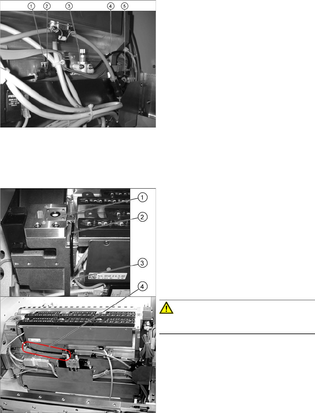
1. Dummy plugs
2. Throttle valve
3. Fine throttle
4. Hose
5. T-piece press-fit connection QSMT-4
► Use the T-piece and PUN hose from the component
trolley feed device to connect the T-piece "press-fit
connection QSMT-4" [03046434-xx] (5) with the
PUN-CM 4x0.75 40 mm [03046289-xx].
► Fit the "Fine throttle GRO-QS-4-LF"
[03045754-xx] (3) with the screws "DIN912 M3x18 -
A2-70" [03045034-xx] onto the "holding plate for
throttle" [03046270-xx] and then fix all this to the tape
feed channel with the screws "DIN7981 ST3.5x6.5-C-
H-A2" [03046777-01] (see photo).
► Remove the "Plug QSC-4H" [00330249-xx] for set-
ting the air blast (see photo).
► Use the two T-pieces to connect the throttle valve
with the "PUN-CM 4x0.75 70 mm" - hoses
[03046291-xx].
1. Nozzle station
2. Hose PUN-CM 4x0.75 420 mm
3. Cable clamp
4. Hose run correctly
► Fit the nozzle station [03045404-xx] (1) with the two
screws "DIN7991 M4x20 - 8.8" [00333782-xx].
► Run the long hose "PUN-CM 4x0.75 420 mm"
[03046432-xx] (2) up to the T-piece (see photo).
► Secure this hose with a cable clamp "Clamp Panduit
CC S12-S08 D3.1 b 8.2" [00368063-xx] (3) and a
screw "DIN912 M3x6 - A2-70" [03045028-xx].
CAUTION!
Make sure that the hose is run in front of the holding plate
for the 1-wire hub (4).
Service Work
3.5.7 Installation and Height Adjustment of Nozzle Station (Description for Docking Unit [03015680-06] with 1-Wire-Hub) C&P20 Nozzle Changer
Service Manual SIPLACE X Series 149
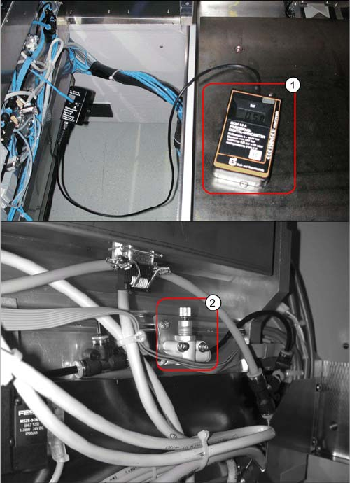
Compressed air setting
1. Measuring device
2. Fine throttle
► Connect the compressed air measuring device to the
T-piece (plug).
► Use the fine throttle to set a pressure of 0.5 bar.
Service Work
C&P20 Nozzle Changer 3.5.8 Installation and Height Adjustment of Nozzle Station (Description for New
150 Service Manual SIPLACE X Series
3.5.8
3.5.8 Installation and Height Adjustment of Nozzle Station (Description for New Docking Unit [03015680-07] with CAN Nodes (Control Board Tape Cutter)
Installation and Height Adjustment of Nozzle Station (Description for New Docking Unit
[03015680-07] with CAN Nodes (Control Board Tape Cutter)
► Dismantle the cover plate from the COT insert.
► If you have not already done so, replace the plug QSC-6H on the solenoid valve feed control with
the "Y press-fit connection with push-on socket QSY-6H-4" [03055792-xx].
► Connect the "Hose PUN4 125 mm" with the Y press-fit connection and the "Valve for nozzle station
assembly" [03055785-xx].
The second opening on the Y press-fit connection needs to be connected with the compressed air
hose of the nozzle changer.
► Connect the "hose PUN4 125 mm" with the "Valve for nozzle station assembly" and the nozzle sta-
tion.
► Connect the cable "Cable feed X series: nozzle station" [03053223-xx] which has already been con-
nected in the COT insert with the "valve for nozzle station assembly."
► Fix the "Valve for nozzle station assembly" with two DIN912-M3x16 screws to the COT insert, as
shown in the diagram above.
NOTICE
Moving the COT insert
Depending on the installation location (one gantry placement area) you may need to loosen the
COT insert and move it outwards. Read the applicable service manual for this. After completion
of work, this needs to be fixed into place again and all attached parts (nozzle changer) must be
remeasured.
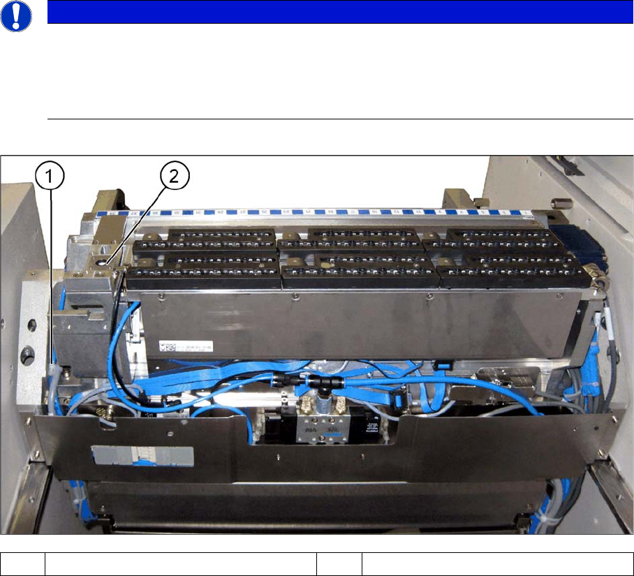
(1) Cable clamp (2) Nozzle station