00194440-10_SM_X-Series_Customer_en.pdf - 第292页
Settings Axis Control 5.2.3 C&P6/12 292 Service Manua l SIPLACE X Series C&P6 - for DP axis, 200 digits C&P6 - for DP axis, 7200 digits Travel curves for DP axis, 200 dig its for C&P6 1. Current tar get v…
Settings
5.2.3 C&P6/12 Axis Control
Service Manual SIPLACE X Series 291
C&P12 - signal for DP axis, 100 digits
12er C&P head DLM2 - signal for DP axis, 3600 digits
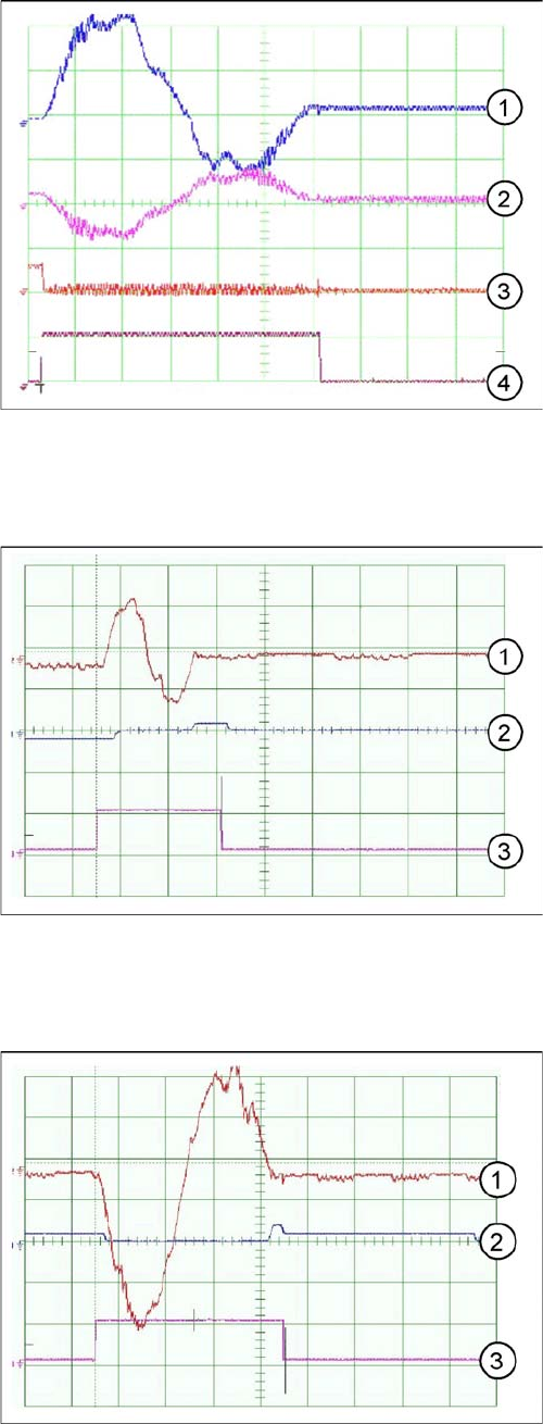
Dynamic signals for DP axis, example of C&P6
1. Control signal (at V nom. axis test box)
2. Uncommutated current signal at axis adapter
3. Deviation of position
4. End signal
Travel curves for DP axis, 100 digits for C&P12
1. Current target value: 200 mV/Div
2. Position deviation: 500 mV/Div
3. End signal
Time basis: 5ms/Div
Path: 100 digits
Travel curves for DP axis, 90 degrees rotation, C&P12
1. Current target value: 200 mV/Div
2. Position deviation: 500 mV/Div
3. End signal
Time basis: 10ms/Div
Path: 3600 digits
Settings
Axis Control 5.2.3 C&P6/12
292 Service Manual SIPLACE X Series
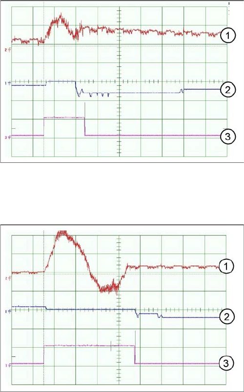
C&P6 - for DP axis, 200 digits
C&P6 - for DP axis, 7200 digits
Travel curves for DP axis, 200 digits for C&P6
1. Current target value: 100 mV/Div
2. Position deviation: 500 mV/Div
3. End signal
Time basis: 20ms/Div
Path: 200 digits
Travel curves for DP axis, 90 degrees rotation, C&P6
1. Current target value: 200 mV/Div
2. Position deviation: 500 mV/Div
3. End signal
Time basis: 20ms/Div
Path: 7200 digits
Settings
5.2.4 C&P20 Axis Control
Service Manual SIPLACE X Series 293
5.2.4
5.2.4 C&P20
C&P20
5.2.4.1
5.2.4.1 Overview of Axis Control for Star, Z and DP Axis
Overview of Axis Control for Star, Z and DP Axis
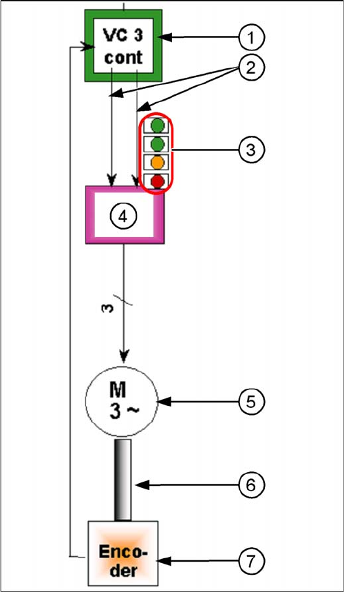
Example: axis control star axis
The closed-loop control system for control of the head
axes consists of the following parts. The differences be-
tween the head axes will be explained later in this chap-
ter.
▪ Axis card A363 with VC3 controller or A364
▪ Servo card (SDS)
▪ Motor
▪ Measurement system (incremental scale and encod-
er)
1. Axis controller board A363 with VC3 controller (VC =
Velocity Commutation)
2. Control signals I target "W" and I target "U"
3. LEDs on servo amplifier:
4. Servo amplifier
5. 3 phase AC motor.
6. Between the motor and the incremental encoder
there is a fixed mechanical connection.
7. Read unit: transmits the exact position of the axis to
the axis card. The track signals are the only feedback
signals for the axes.
The servo board controls the motor directly.