00194440-10_SM_X-Series_Customer_en.pdf - 第202页
Service Work COT Insert HF R2 3.8.1 Replacing the COT Insert Assembly [030008 11- xx] 202 Service Manua l SIPLACE X Series 3.8 3 . 8 C O T I n s e r t H F R 2 COT Insert HF R2 3.8.1 3 . 8 . 1 R e p la c in g t h e C O T …
Service Work
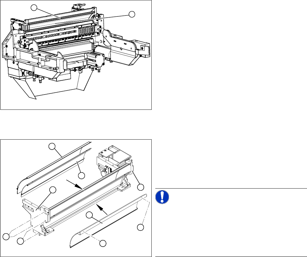
3.7.8 Replacing the Baffles [03002191-xx] X-Series COT Insert
Service Manual SIPLACE X Series 201
3.7.8
3.7.8 Replacing the Baffles [03002191-xx]
Replacing the Baffles [03002191-xx]
Overview
Removal/installation
► Replace the individual baffles as described below:
► Loosen the four screws (5) fastening the "baffle, outside" on both side panels.
► Loosen the four screws(6) fastening the "baffle, inside" on both side panels.
► Loosen the two screws (7) fastening the baffle insert.
1. Empty-tape duct assembly
2. Baffles
1
2
1. Baffle outside
2. Baffle, inside
3. Baffle insert
4. Side panels
NOTICE!
Inner baffle
When using tape reels with deep pockets, you may need
to remove the inner (center) baffle (2). Refer to the oper-
ating instructions for the relevant SIPLACE machine.
All screws are accessible in the installed state. The baf-
fles can therefore be replaced inside the machine.
1
4
3
2
7
6
5
4
7
Service Work
COT Insert HF R2 3.8.1 Replacing the COT Insert Assembly [03000811-xx]
202 Service Manual SIPLACE X Series
3.8
3.8 COT Insert HF R2
COT Insert HF R2
3.8.1
3.8.1 Replacing the COT Insert Assembly [03000811-xx]
Replacing the COT Insert Assembly [03000811-xx]
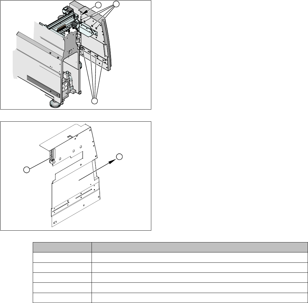
Remove the safety cover.
Removing the COT insert
► Open the cable duct in which all connections cables and compressed air hoses have been run.
► Carefully pull these cables and hoses out through the opening in the machine base, until you can
access all the press-fit connections.
► Mark the allocation of all press-fit connections so that you can restore the connections later, with the
new cables.
► The following table shows the plugs and cables for each location:
► Remove the cover for the press-fit connections (3).
► Remove the screws (1) / (2) on the safety cover.
► Unplug the press-fit connections (1) and disconnect
the ground cable. Please see the table below for plug
and cable allocation details.
► Pull out the safety cover (2).
► Disconnect the compressed air hose for the COT in-
sert.
► Seal the hose with a plug.
1
3
2
1
2
Connector Cable
X2*h [03006857]-W2
X120 [03005794]
X1*h [03006857]-W3
X118 [03003973]
X119 [03003974]
Service Work
3.8.1 Replacing the COT Insert Assembly [03000811-xx] COT Insert HF R2
Service Manual SIPLACE X Series 203
Location COT insert
Designator / Cable
Basic Machine
Plug / Cable
1 Power supply 03001288 X111 03002491
Signaling 03006857 X112 03002541
Security 03006858 X113 03002542
Nozzle changer 03001295 X114 03002543
CAN-IN 03006856 X115 03010051
CAN-Out 03006856 X116 03010050
2 Power supply 03001288 X121 03002492
Signaling 03006857 X122 03002530
Security 03006858 X123 03002531
Nozzle changer 03001295 X124 03002532
CAN-IN 03006856 X125 03010053
CAN-Out 03006856 X126 03010054
3 Power supply 03001288 X131 03002493
Signaling 03006857 X132 03002534
Security 03006858 X133 03002535
Nozzle changer 03001295 X134 03002536
CAN-IN 03006856 X135 03010056
CAN-Out 03006856 X136 03010057
4 Power supply 03001288 X141 03002494
Signaling 03006857 X142 03002546
Security 03006858 X143 03002547
Nozzle changer 03001295 X144 03002548
CAN-IN 03006856 X145 03010051
CAN-Out 03006856 X146 03010052
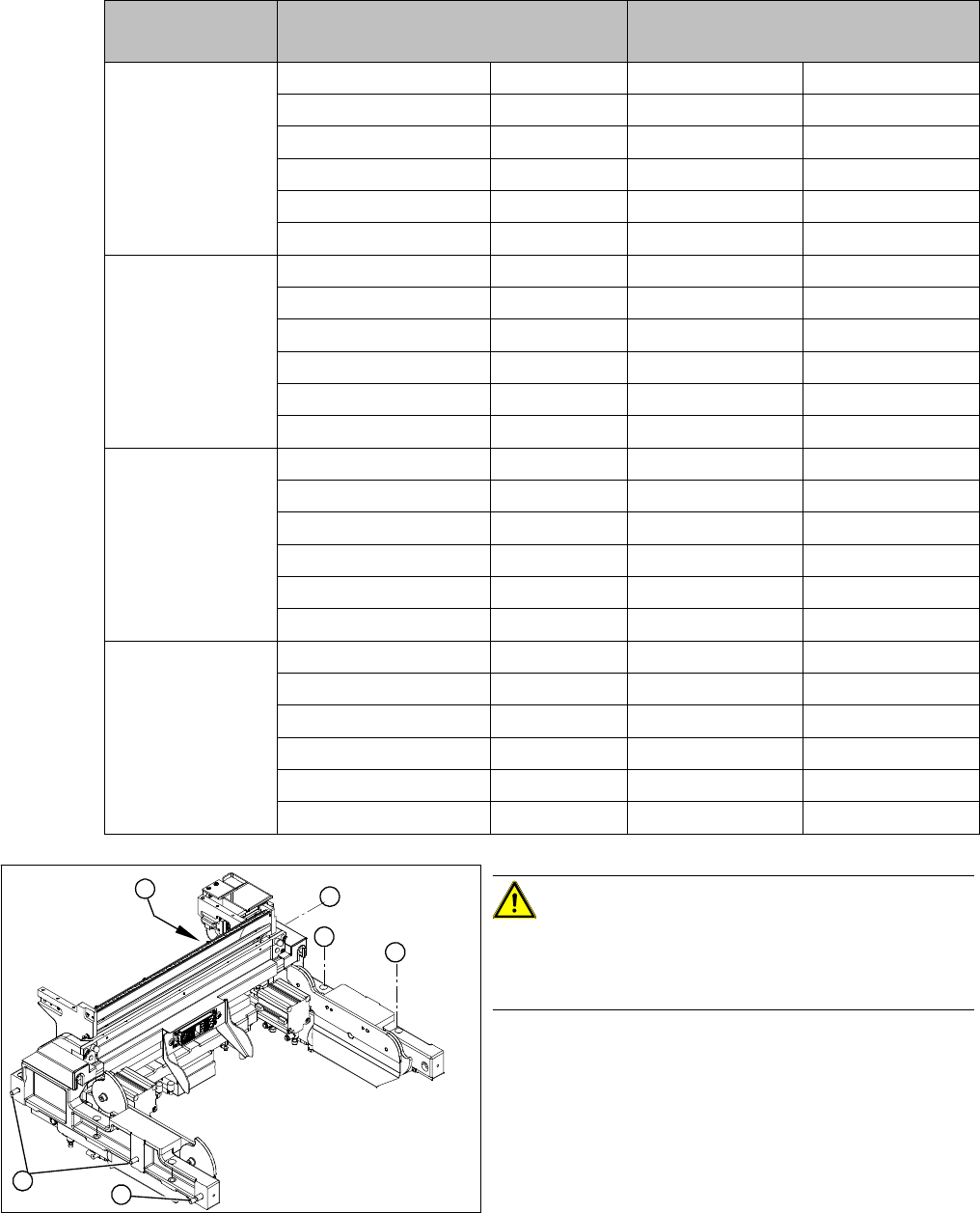
CAUTION!
Heavy machine part!
The COT insert is heavy. You will need to enlist the help
of a second strong person to help you lift it out.
► Loosen the screws fastening the COT insert (1).
► Loosen the fitting screw (2) on the inside of the ma-
chine.
► Lift the complete COT insert out of the machine and
place it on a suitable surface (four wooden blocks
etc.).
► Make sure that you do not damage any valves, con-
nection cables, hoses etc.
► Fit the new COT insert and reconnect all cables.
► Run the cables and hoses through the opening in the
machine base.
1
1
1
1
2
1