00194440-10_SM_X-Series_Customer_en.pdf - 第221页
Service Work 3.9.7 Replacing the Cutter Blades Cutter Service Manual SIPLACE X Series 221 3.9.7 3 . 9 . 7 R e p la c in g t h e C u t t e r B la d e s Replacing the Cutter Blades Parts, equipment and tools Select the rig…
Service Work
Cutter 3.9.6 Replacing the Proximity Switch (FSE) [00332894-xx]
220 Service Manual SIPLACE X Series
Removal/installation
3.9.6
3.9.6 Replacing the Proximity Switch (FSE) [00332894-xx]
Replacing the Proximity Switch (FSE) [00332894-xx]
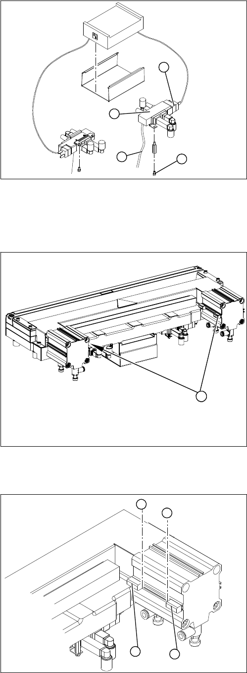
Overview
Removal/installation
1. Solenoid valve assembly
► Loosen the compressed air connections (3) on the
solenoid valve.
► Unplug the press-fit connection (2) on the solenoid
valve connection cable.
► Loosen the screws (4) holding the solenoid valve in
place and remove the solenoid valve.
► Mount the new solenoid valve and make the press-fit
connection to the valve.
Attach cables ties, if necessary (strain relief).
1
4
3
2
1. Two proximity switches each on the short-stroke cyl-
inder
1
► Use a permanent marker to mark the exact installa-
tion position (3) of the proximity switch (1) or (2) on
the short-stroke cylinder.
► Loosen the screw fastening the proximity switch to
the short-stroke cylinder.
► Unthread the connection cable to the control unit.
► Install the proximity switch precisely in the position (3)
you marked with the permanent marker on the short-
stroke cylinder.
► Secure the fastening screws with locking varnish..
► Reconnect to the electricity supply.
► Check the switching points of the proximity switches.
1
2
3
3

Service Work
3.9.7 Replacing the Cutter Blades Cutter
Service Manual SIPLACE X Series 221
3.9.7
3.9.7 Replacing the Cutter Blades
Replacing the Cutter Blades
Parts, equipment and tools
Select the right set of blades.
We recommend the following additional spare parts:
▪ 2x blade cover (cutter HF) [03000553-xx] (cover for screws of movable blades)
▪ 2x ISO4762-M5x35-12.9, geomet 321+VL [03057290-xx] (screws for movable blades)
▪ 2x articulated joint (cutter HF) [03000518-xx]
▪ 2x DIN71412-BM6 [03036943-xx] (lubrication nipple)
Consumables required:
▪ Lubricant grease Klüber BEM 34-132 tin 1 kg [00374565-xx] (identical to the lubricant grease used
on the guide carriage of the gantry)
▪ Interflon Fin Grease [03020782-xx]
▪ LOCTITE 243 screw locking varnish [00334892-xx]
Tools required
▪ Extra protection gloves, leather [00091001-xx]
▪ Torx screwdriver ESD 1.0-5.0 Nm [03078400-xx]
▪ Torque wrench 2.5 - 25 Nm [00376625-xx]
▪ Bit holder for TorqueVario screwdriver [03078706-xx]
▪ Socket-head bit size 3-6
▪ Fork wrench, size 10
▪ Feeler gauge
▪ Brush
▪ Cloth
▪ Two large parallel clamps and a sturdy table with even surface, to clamp down the dismantled cutter
CAUTION
Risk of injury!
There is a high risk of injury from the blades and the tape deflector.
► Wear appropriately thick protective gloves!
► Never reach into the cutter from below or into the empty-tape duct from above.
► Make sure that no-one can injure themselves on the cutter after it has been dismantled and
placed next to the machine!
Machine Tape cutter, pneumatic Function status Set of blades
X series, SX4, DX4, X
series S
03066690-xx
(without CAN nodes)
-01 03009259-xx
HF, X series 03000487-xx -01 to -03 03000501-xx
-04 to -05 03009259-xx
X Series 03019941-xx
(with control unit)
-01 03009259-xx
03052900-xx
(with CAN nodes)
-01 to -02 03009259-xx
Service Work
Cutter 3.9.7 Replacing the Cutter Blades
222 Service Manual SIPLACE X Series
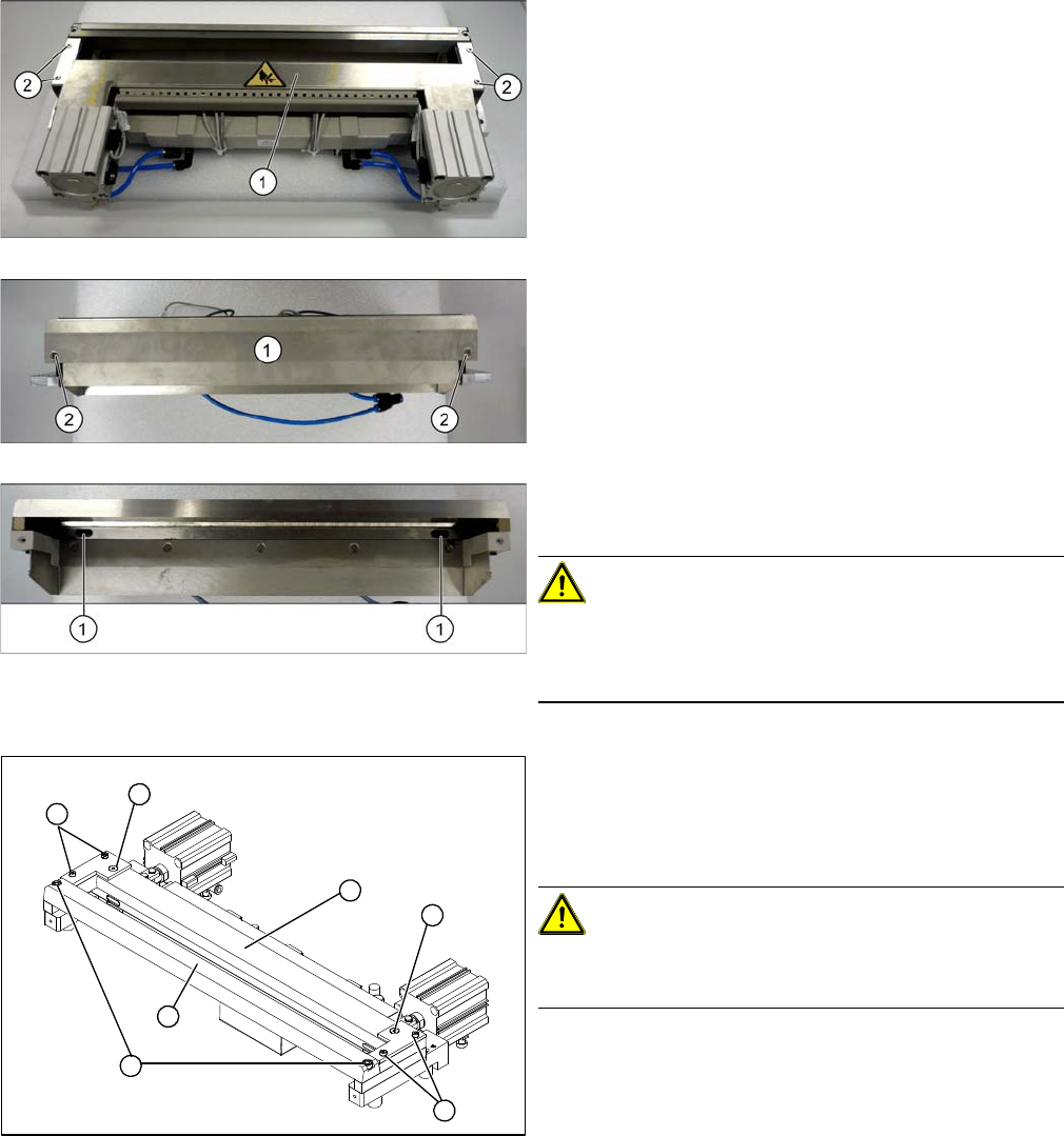
Removal
► Remove the cutter from the machine. For details,
read the relevant section of this instruction manual.
► Loosen the screws (2) fastening the top cover
plate (3) and then remove the cover plate.
► Loosen the screws (2) fastening the baffle plate (3) to
the back of the cutter and remove the baffle plate.
► Remove the caps over the fastening screws (1) on
the movable blade and loosen the blade.
CAUTION!
Risk of injury!
There is a risk of injuring yourself on the cutting edge of
the blades.
Cutter (using example of X series)
► Loosen and remove the two screws (1) fastening the
stationary blade (2).
► Loosen the screws fastening the left and right tape
deflectors (3) above the moveable blade.
CAUTION!
Do not loosen all screws!
Do not loosen these two screws (4)
► Remove the tape deflector holder with the tape de-
flector (5) and carefully place the whole unit down
(with the tape deflector facing upwards).
4
3
5
1
4
3
2