00194440-10_SM_X-Series_Customer_en.pdf - 第214页
Service Work Cutter 3.9.2 Replacing the Cutter [03052900-xx] on the X-Series COT Insert 214 Service Manua l SIPLACE X Series Installing the cutter ► Remove the two fixtures (1) on the left and right and attach the se wit…

Service Work
3.9.2 Replacing the Cutter [03052900-xx] on the X-Series COT Insert Cutter
Service Manual SIPLACE X Series 213
3.9.2
3.9.2 Replacing the Cutter [03052900-xx] on the X-Series COT Insert
Replacing the Cutter [03052900-xx] on the X-Series COT Insert
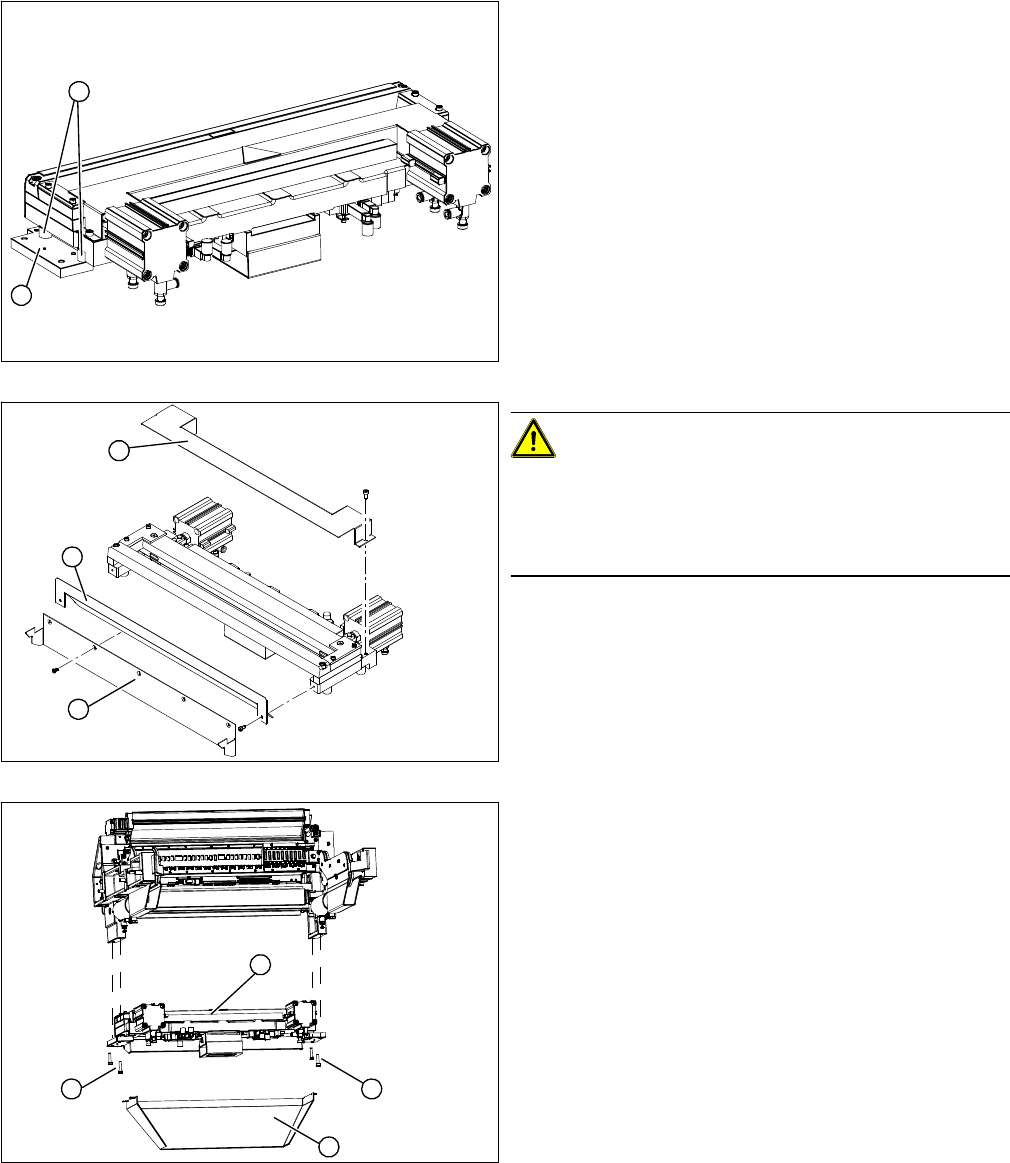
Removing the cutter
► Install the empty-tape duct (1). Align the empty-tape
duct in the center.
► Clamp the back cover plate into the duct. When
closed, it should prevent components from falling
through.
► Install the centering bar (2) and the bracket (3) with
the ODU connector (4). Make sure you do not dam-
age the cables and hoses.
CAUTION!
Make sure that assembly is performed correctly!
You must be able to move the ODU connector.
► Fit the complete COT insert into the machine again.
► Calibrate the nozzle changer, including its pickup
height.
1
3
4
2
1. Cutter
2. Pneumatic cylinder
3. Waste tape container
4. Control unit
The cutter (1) can be removed without dismantling the
COT insert.
► Loosen the compressed air connections for the short-
stroke cylinder (2) at the coupling.
► Remove the cover on the control unit (3) and unplug
the electrical connections leading to the control unit
(3).
► Loosen the four screws fastening the waste tape con-
tainer (4) and remove this container.
WARNING!
Risk of injury when releasing the fixtures!
The cutter is only held by the fastening screws and is not
supported by other parts. If the four fastening screws are
loosened, the cutter will fall down and out of the machine.
► Make sure that no one is under the cutter!
► Support the cutter by placing a suitable object
(height-adjustable support or chair) under it.
► Loosen the four fastening screws (1) on the cutter
mount.
► Carefully lower the cutter and lift it out of the machine.
2
3
4
1
2
1
1
Service Work
Cutter 3.9.2 Replacing the Cutter [03052900-xx] on the X-Series COT Insert
214 Service Manual SIPLACE X Series
Installing the cutter
► Remove the two fixtures (1) on the left and right and
attach these with the spacer sleeves (2) to the new
cutter.
⇨ There may also be other shims in-between, which
will then need to be fitted back in the correct posi-
tion after service work.
► Carefully lift the cutter onto the spacer sleeves. Use
the spacer disks if provided.
► Tighten all four fastening screws.
CAUTION!
There is a risk of injuring yourself on the cutting edge of
the blades.
For this reason, the deflector plate (2), cover (1) and pro-
tective sheet (3) must be left mounted in place.
► Move the cutter (1) into its installation position, using
the support/chair for assistance.
► Carefully lift the cutter (1) into the planned position.
► Tighten all four fastening screws (2).
► Reconnect to the electrical and compressed air sys-
tems.
► Fit the waste tape container (3).
2
1
1
3
2
2
1
3
2
Service Work
3.9.3 Replacing the Articulated Joint on the Short-Stroke Cylinder [03000518-xx] Cutter
Service Manual SIPLACE X Series 215
3.9.3
3.9.3 Replacing the Articulated Joint on the Short-Stroke Cylinder [03000518-xx]
Replacing the Articulated Joint on the Short-Stroke Cylinder [03000518-xx]
Removing the articulated joint
► Dismantle the COT insert and the cutter.
► Remove the protective plate (2) and the baffle plate
(3).
► Remove the cover plate (1).
► Remove the caps (4) on the fastening screws.
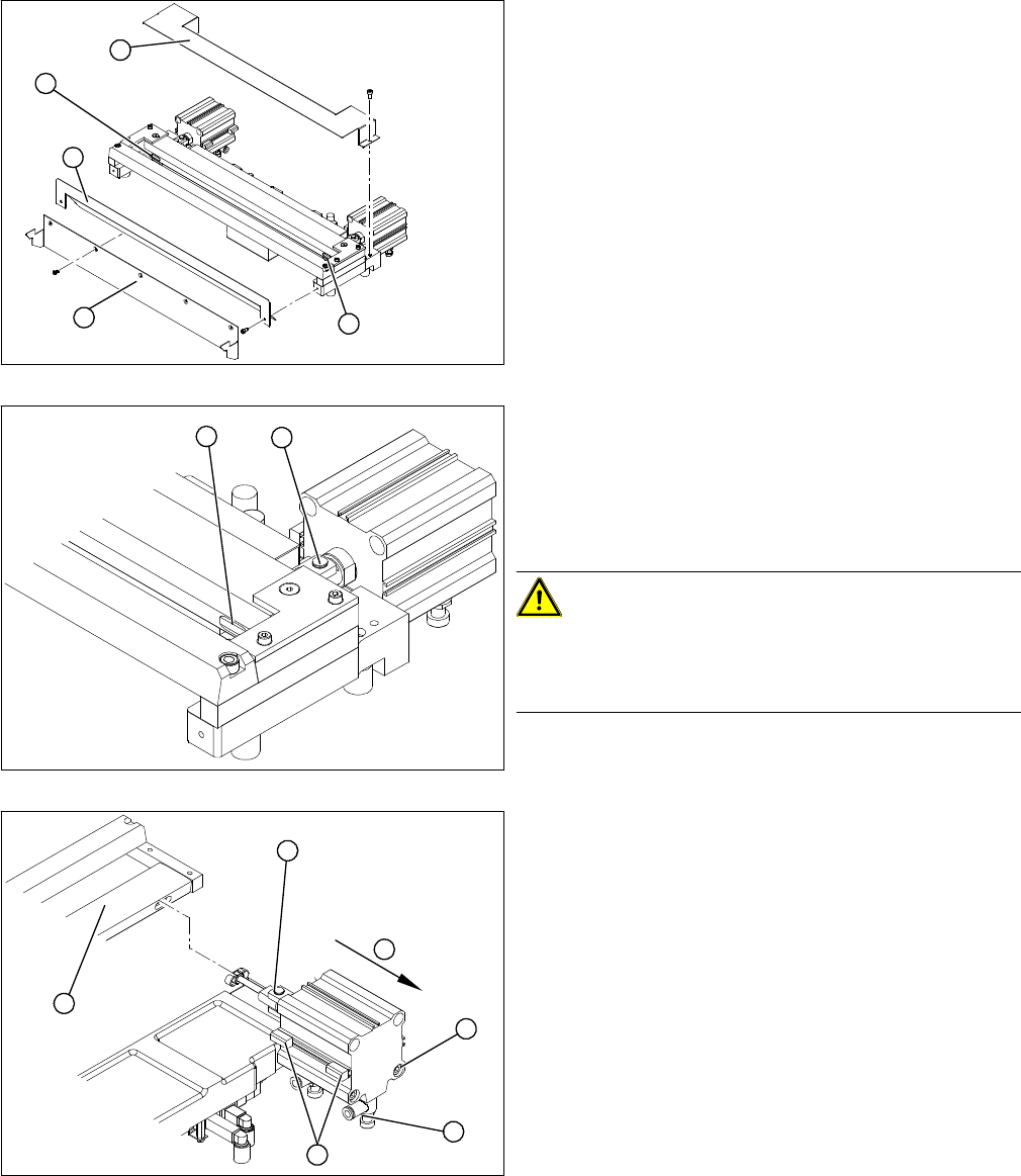
1. Articulated joint on the short-stroke cylinder
2. Fastening screw on moveable blade.
► Loosen the screw (2) holding the moveable blade.
CAUTION!
Risk of injury!
There is a risk of injuring yourself on the cutting edge of
the blades.
► Use a permanent marker to mark the exact installa-
tion position of the proximity switch (1) on the short-
stroke cylinder. Mark the hoses.
► Loosen the screws fastening the two inductive prox-
imity switches (1) to the short-stroke cylinder.
► Remove the compressed air connections (2) on the
short-stroke cylinder.
► Remove the two screws (3) holding the short-stroke
cylinder.
► Pull the short-stroke cylinder (4) and the articulated
joint screwed into it (5) out of the cutter set (6).
4
1
4
3
2
1
2
1
6
5
4
3
2