00194440-10_SM_X-Series_Customer_en.pdf - 第224页
Service Work Cutter 3.9.7 Replacing the Cutter Blades 224 Service Manua l SIPLACE X Series Installation ► Use an SW 10 o pen-ended wrench to push against the relevant joi nt ( 3 ) and then tighten bot h screws (2) to a t…
Service Work
3.9.7 Replacing the Cutter Blades Cutter
Service Manual SIPLACE X Series 223
Installation – requirements
▪ Wear appropriately thick protective gloves!
▪ Make sure all parts are clean before installing them.
▪ The new blades are covered with a fine lubrication film.
Do not use fat dissolving agents on the blades (risk of rust film forming).
The blades may only be greased with the lubricants described in the maintenance manual.
Any other lubricant would impair the movement of the moveable blade.
▪ If the new blades are not clean, carefully clean them (wear protective gloves) with a clean brush or
a well folded, clean and dry cloth.
Do not use fat dissolving agents!
Preparation
► Make sure the cutter is in the correct rotary position (see the slant of the blade).
► Check the positioning of the individual blades to one another.
► Before installation, lubricate the sliding side surfaces of the moveable blade with Klüber BEM 34-132
and make sure that the recesses are filled. These will be refilled later on during maintenance with
the lubrication adapter.
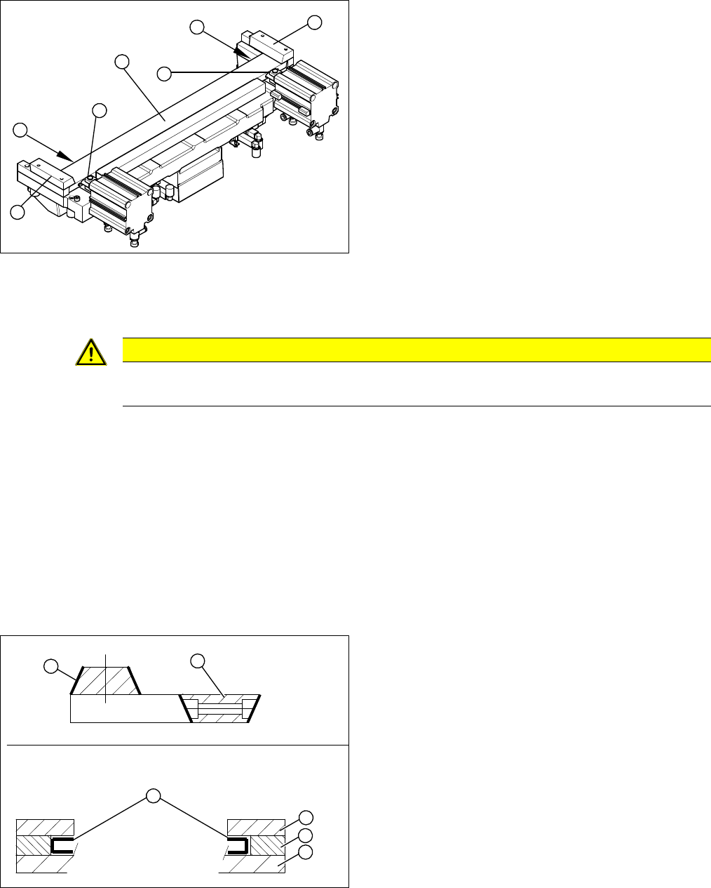
Cutter (using example of X series)
► Remove the right-hand holding-down device (1) and
the left holding-down device (2), plus the spacers be-
low.
► Use an SW 10 open-ended wrench to push against
the joint (3), while loosening the hexagon socket-
head screw of the joint (4) in the moveable blade.
This may require more strength than usual as the
screws have been secured with Loctite no. 243.
► Grasp both ends of the moveable blade (5) with the
protective gloves and pull it upwards and out.
3
4
1
5
4
3
2
CAUTION
Risk of injury!
There is a high risk of injury from the blades and the tape deflector.
1. Stationary blade
2. Moveable blade
3. Sliding surfaces to be lubricated
4. Holding-down device
5. Spacer
6. Contact surface
1
6
5
4
3
2
Service Work
Cutter 3.9.7 Replacing the Cutter Blades
224 Service Manual SIPLACE X Series
Installation
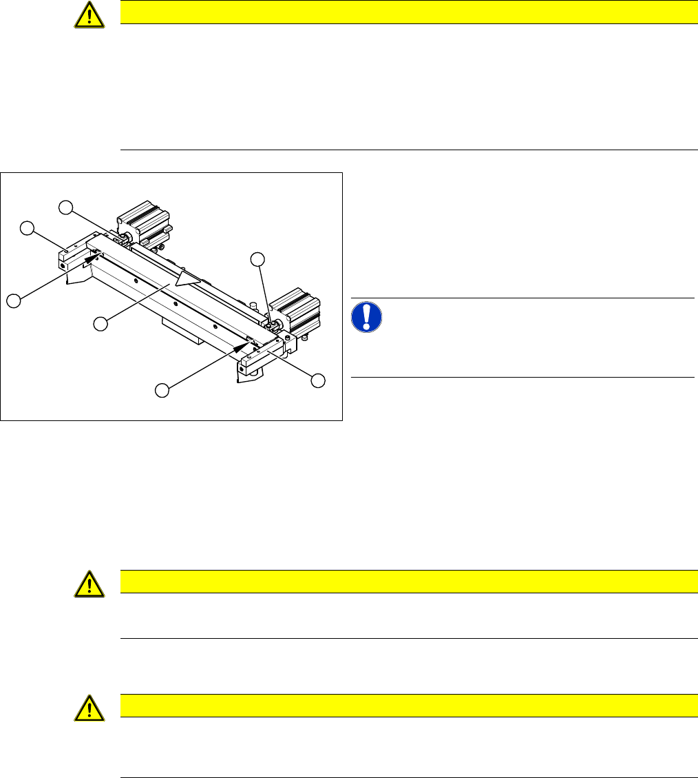
► Use an SW 10 open-ended wrench to push against the relevant joint (3) and then tighten both screws
(2) to a torque of 2.7 – 3.0 N.
► Fit the two caps over the fastening screws on the movable blade.
► Place the two new spacers (4) to the left and right of the moveable blade. The spacer side marked
with a number must face away from the blade.
► Lubricate the contact/slide surfaces for the moveable blade, as described in the section "Prepara-
tions".
CAUTION
Observe the relevant torque during installation:
M3: 1.0-1.3 Nm
M4: 2.7-3.0 Nm
M5: 5.5-6.0 Nm
M6: 9.5-10.2 Nm
The torques depend on the screw types used. Always use the original screws.
Cutter (using example of X series)
► Correctly insert the moveable blade (1) into the cutter
and shift it along to its original installation position.
► Apply Loctite no. 243 to the two M4 screws, to fasten
the joint in the moveable blade.
► Insert the screws (2) into the left and right holes, pro-
vided in the moveable blade.
NOTICE!
Make sure that the joint (3) can slide into the slot (= anti-
twist function) in the moveable blade without obstruction.
2
3
4
1
4
3
2
CAUTION
The spacers and blades are matched!
► Do not use any spacers from other sets of blades.
CAUTION
Only apply grease to the exact points required!
The overlapping cutting surfaces may only be greased with Interflon Fin Grease [03020782-xx].
Also observe the preventive maintenance manual for your machine.
Service Work
3.9.7 Replacing the Cutter Blades Cutter
Service Manual SIPLACE X Series 225
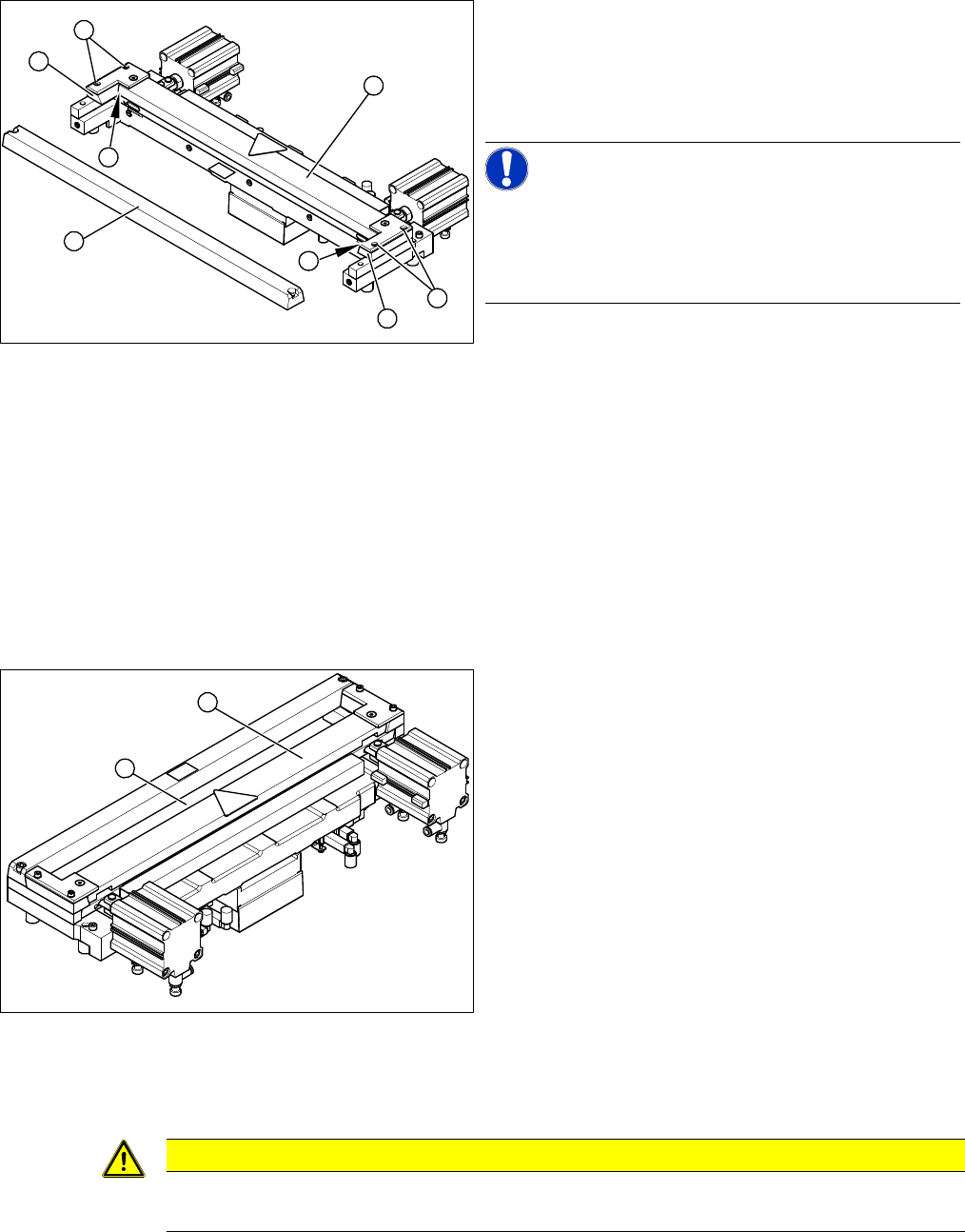
► Insert the dismantled wiper unit (3) and the downholders back in and tighten loosely with the four
hexagon socket-head screws (4).
► Push the spacers (with inserted feeler gauges) as far as possible in the direction of the moveable
blade. The maximum permissible gap is 1.0 mm.
► Now tighten the four screws (4) crosswise at the downholder (observe torque).
► Remove the two feeler gauges.
► Insert the new stationary blade (5) in the correct position and screw tight.
Final Work:
If the gap is correct:
► Fit the baffle plate and cover plate. Make sure that the edges are parallel.
► Remove the clamps form the cutter/ remove the cutter from the assembly plate.
Cutter (using example of X series)
► Place a feeler gauge (0.5 - 1.0 mm thickness) on the
left and right, between the spacer and the front of the
moveable blade (1).
► Place the previously removed holding-down device
(2) onto the new spacers.
NOTICE!
Holding-down device
The holding-down devices with function status 03 are de-
signed for use with cutters of function status -04 (= with
tape deflector).
1
2
4
1
5
4
3
2
Cutter (using example of X series)
► Use a feeler gauge to check the gap between the
tape deflector (1) and the moveable blade (2), along
the entire length and width of the blade.
⇨ The 0.05 mm feeler gauge should fit through the
gap.
⇨ The 0.25 mm feeler gauge should not fit through
the gap.
If the gap is not correct, check:
▪ Whether the wrong holding-down device has been in-
stalled (with function status < 03)
▪ The holding-down devices are those designed for
cutters with function status -04 (= with tape deflector)
▪ Whether the blades, tape deflector etc. were cleaned
before installation
1
2
CAUTION
Check how the cables are run!
Make sure that the cables and hoses are not pinched or subjected to excess strain.