00194440-10_SM_X-Series_Customer_en.pdf - 第238页
Service Work Docking Station for X-Series Component Trolley 3.12.4 Replacing the Locking Lever [030251 04-XX] 238 Service Manua l SIPLACE X Series 3.12.4 3 . 1 2 . 4 R e p la c in g t h e L o c k in g L e v e r [ 0 3 0 2…
Service Work
3.12.3 Replacing the Locking Unit Short-Stroke Cylinder [03034831-XX] Docking Station for X-Series Component Trolley
Service Manual SIPLACE X Series 237
3.12.3
3.12.3 Replacing the Locking Unit Short-Stroke Cylinder [03034831-XX]
Replacing the Locking Unit Short-Stroke Cylinder [03034831-XX]
Parts, equipment and tools
▪ Short-stroke cylinder [03034831-xx]
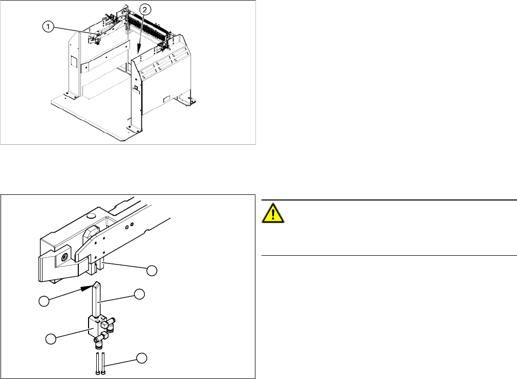
Overview
Removal
Installation
► Install the locking slider (3) on the new short-stroke cylinder (2).
► Reconnect to the compressed air supply.
► Clean the locking sliders (3) and the guidance block (5) with a clean, lint-free cloth and lubricate both
slightly with Unisilikon.
► Move the locking slider (3) into the guidance block, so that the beveled side (4) is pointing to the front
(in the direction of travel). This is important when moving the component trolley in.
► Fit the short-stroke cylinder with the two fastening screws.
► Switch the compressed air supply on again and check that the left and right locking sliders move out
at the same time.
► If necessary, adjust the throttle valve (6) on the short-stroke cylinder.
1. Installation position of left locking unit
2. Installation position of right locking unit
CAUTION!
Risk of injury when disconnecting pressurized com-
pressed air lines.
► Switch off the compressed air supply.
► Loosen the two screws (1) fastening the short-stroke
cylinder (2).
► Pull the short-stroke cylinder (2) and the locking slider
(3) downwards and out of the guidance block (5).
► Loosen the pneumatic connections on the short-
stroke cylinder.
► Unscrew the locking slider (3) from the short-stroke
cylinder (2).
5
1
4
3
2
Service Work
Docking Station for X-Series Component Trolley 3.12.4 Replacing the Locking Lever [03025104-XX]
238 Service Manual SIPLACE X Series
3.12.4
3.12.4 Replacing the Locking Lever [03025104-XX]
Replacing the Locking Lever [03025104-XX]
Parts, equipment and tools
▪ Locking lever [03025104-xx]
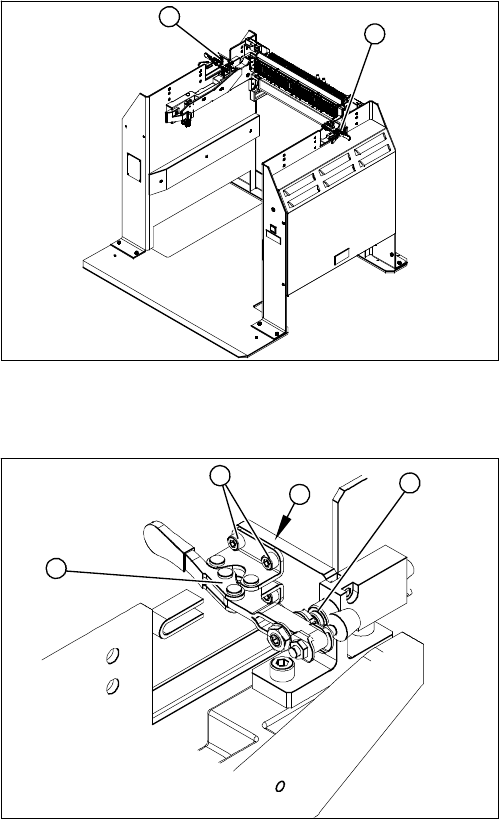
Overview
Removal
Installation
► Loosely screw in the new locking lever.
► Align the locking lever to the edge (3) and tighten the four fastening screws.
► Check that the limit switch (4) is actuated when the locking lever is closed. Correct the position of
the locking lever, where necessary.
► Check the position end switch function, by trying out the locking procedure.
1. Locking lever – on the left side
2. Locking lever – on the right side
1
2
1. Locking lever
2. Four fastening screws
3. Position end switch
► Loosen the four screws (2) (two each at the top and
bottom) fastening the locking lever (1).
► Remove the locking lever.
4
3
2
1
Service Work
3.12.5 Replacing the Positions End Switch of the Component Trolley Locking Device [03033395-XX] Docking Station for X-Series Component
Service Manual SIPLACE X Series 239
3.12.5
3.12.5 Replacing the Positions End Switch of the Component Trolley Locking Device [03033395-XX]
Replacing the Positions End Switch of the Component Trolley Locking Device
[03033395-XX]
Parts, equipment and tools
▪ Position end switch [03033395-xx]
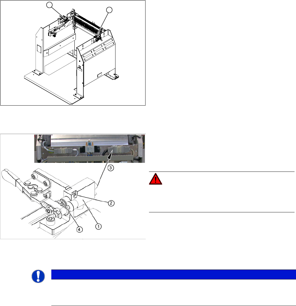
Overview
Removal
► Loosen the two screws fastening the limit switch.
► Open the casing of the connector at the back and label the terminal connections.
► Disconnect the connection cable for the relevant position end switch, in the connector.
► Unthread the connection cable and remove the position end switch.
1. Position end switch – on the left side
2. Position end switch – on the right side
1
2
1. Position end switch with connection cable
2. Two fastening screws
3. Connection cable to connector unit
4. Actuation by locking lever
DANGER!
Switch off the voltage supply
Press the ON/OFF button to switch off and disconnect the
power supply.
NOTICE
Connector for left and right position end switch
► The connection cables for the left and right position end switch are connected to a common
connector.