00194440-10_SM_X-Series_Customer_en.pdf - 第262页
Settings Gantry Settings 5.1.5 Anticrash board 262 Service Manua l SIPLACE X Series 5.1.5 5 . 1 . 5 A n t ic r a s h b o a r d Anticrash board The anticrash board is installed in the axi s unit of all machin es with the …
Settings
5.1.4 Anticrash Function for the A364 Axis Card Gantry Settings
Service Manual SIPLACE X Series 261
5.1.4.5
5.1.4.5 Anticrash Function
Anticrash Function
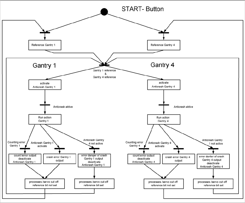
Example of the anticrash function sequence in placement area 1
Settings
Gantry Settings 5.1.5 Anticrash board
262 Service Manual SIPLACE X Series
5.1.5
5.1.5 Anticrash board
Anticrash board
The anticrash board is installed in the axis unit of all machines with the A363 axis card and causes the
main axes to stop immediately in the event of excess speed in the stopper area.
Anticrash board in SIPLACE X
NOTICE
Settings on the anticrash board are not required for SIPLACE X2 machines and machines with
the A364 axis card!
On X3/X4/D3 machines with axis card A363 the proximity sensor between gantry 1 and 4 or the
one between gantry 2 and 3 is active and needs to be adjusted.
This check and this adjustment are not necessary in SIPLACE machines using the A364 axis
controller (in axis unit version 2).
Anticrash board
CAUTION!
Press the EMERGENCY STOP before resetting!
If the anti-crash board issues an error message, press
the EMERGENCY STOP button on the machine and
keep it pressed, while also pressing the reset button (T1)
to reset the error.
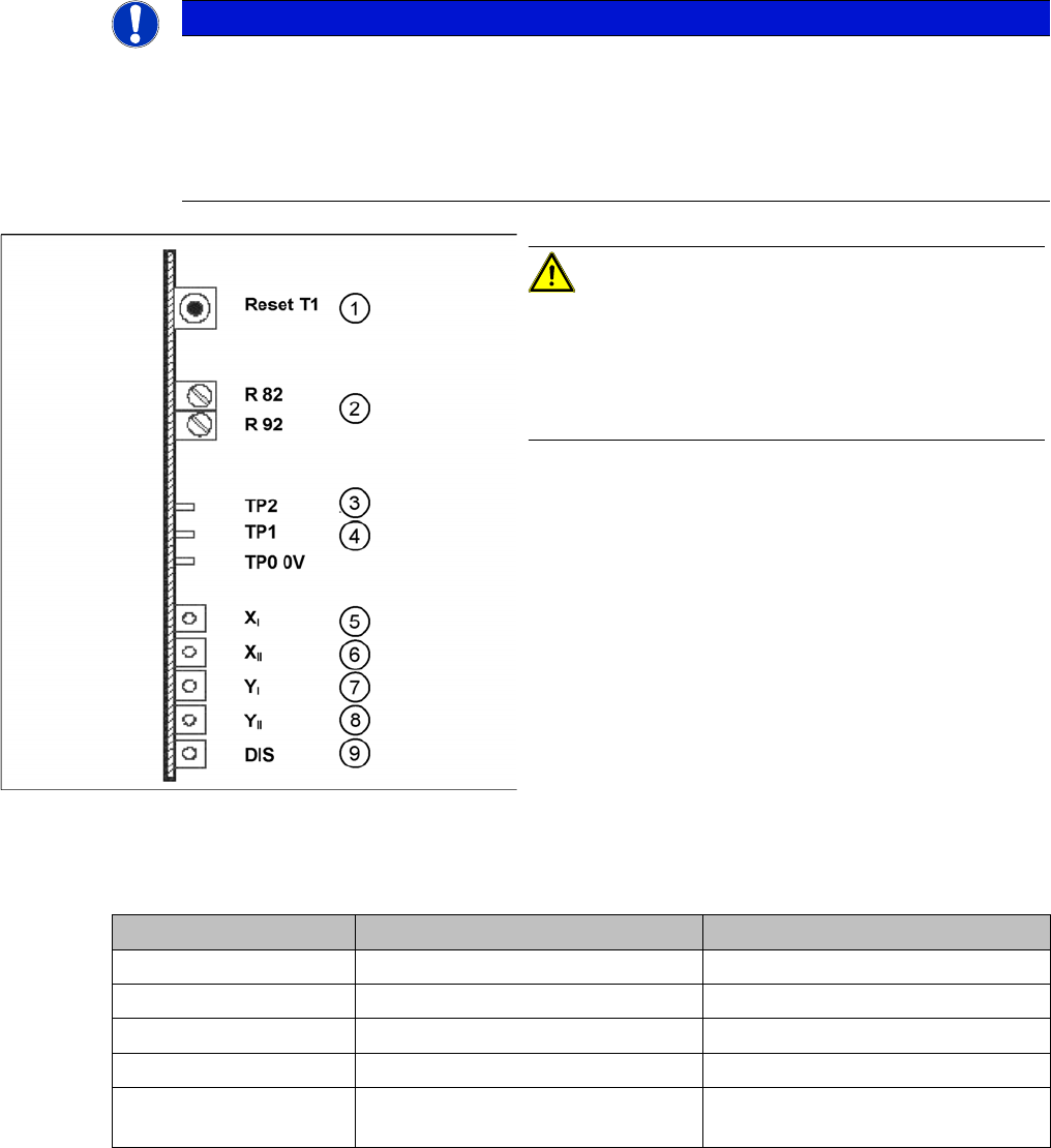
1. T 1-> Reset button
2. R82, R92 = potentiometer
3. TP2 -> speed signal
4. TP1 -> Distance sensor signal
5. LED X
I
-> 1st X axis "malfunction"
6. LED X
II
-> 2nd X axis "malfunction"
7. LED Y
I
-> 1st Y axis "malfunction"
8. LED Y
II
-> 2nd Y axis "malfunction"
9. LED DIS = signals that the distance sensor has trig-
gered (not used for X2)
Description Anti-crash board in axis unit PA 1 Anti-crash board in axis unit PA 2
LED X I 1st X axis X axis, gantry 1 X axis, gantry 2
LED X II 2nd X axis X axis, gantry 4 X axis, gantry 3
LED Y I 1st Y axis Y axis, gantry 1 Y axis, gantry 2
LED Y II 2nd Y axis Y axis, gantry 4 Y axis, gantry 3
LED DIS Either active or inactive, depending
on machine type
Either active or inactive, depending
on machine type
Settings
5.1.5 Anticrash board Gantry Settings
Service Manual SIPLACE X Series 263
5.1.5.1
5.1.5.1 Setting the Sensitivity of the Distance Sensor
Setting the Sensitivity of the Distance Sensor
5.1.5.2
5.1.5.2 Calibrating the Anticrash Board
Calibrating the Anticrash Board
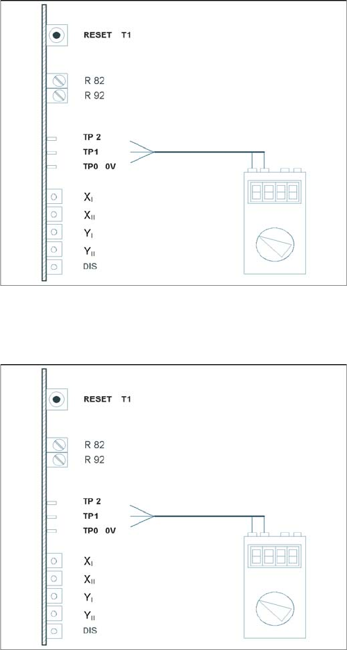
Test setup of anticrash board
► Connect the digital multimeter to the anticrash board
TP 0 (0V) and TP 1 (signal).
► Push the two gantries together.
► Use the adjustment screw to set the voltage on the
distance sensor to 6V - +/- 0.1 V.
► Push the two gantries to a distance of 100 mm.
(elastomeric spring up to countersurface).
► The voltage should be approx. 2V.
Test setup of anticrash board
► Connect the digital multimeter to the anticrash board
at pin TP2 (signal) and at pin TP0 (0V).
► Push the two gantries together.
► Use the potentiometer R82 to set the voltage to 0V-
+/- 0.05 V.
► Push the two gantries together, to a distance of 100
mm +/- 1 mm.
► Use the potentiometer R92 to set the voltage to 0V-
+/- 0.05 V.
► Check the 0V setting again.
► If the value deviates, you will need to calibrate again.