00194440-10_SM_X-Series_Customer_en.pdf - 第227页
Service Work 3.10.2 Replacing the Locking Latch [03069205-xx] X-Series Compon ent Trolley Service Manual SIPLACE X Series 227 3.10.2 3 . 1 0 . 2 R e p la c in g t h e L o c k in g L a t c h [ 0 3 0 6 9 2 0 5 - x x ] Repl…
Service Work
X-Series Component Trolley 3.10.1 Replacing the Fixed/Guide Castors [00341918-xx]
226 Service Manual SIPLACE X Series
► Further installation is performed by following the above instructions in the reverse order.
See also
3.9.2 Replacing the Cutter [03052900-xx] on the X-Series COT Insert [ ➙ 213]
3.10
3.10 X-Series Component Trolley
X-Series Component Trolley
3.10.1
3.10.1 Replacing the Fixed/Guide Castors [00341918-xx]
Replacing the Fixed/Guide Castors [00341918-xx]
Parts, equipment and tools
▪ Fixed castor [00341918-xx] or
Guide castor [03004958-xx]
▪ Second person
Removal/Installation
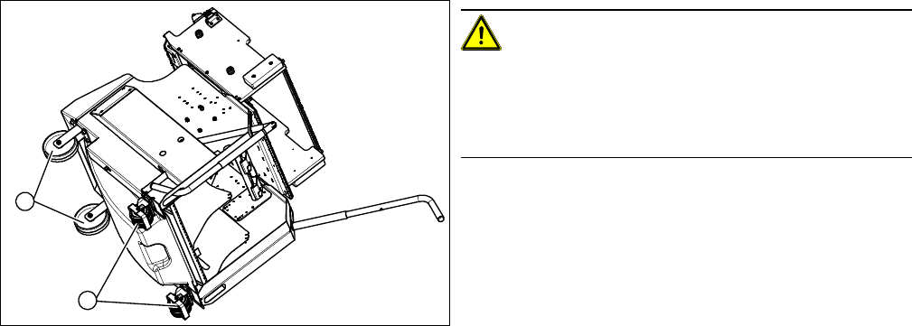
CAUTION!
Heavy machine part!
The component trolley must be placed on one side in or-
der to remove the fixed/guide castors. You will need two
people to perform this task.
► Move the component trolley out of the machine.
► Place the component trolley on its side, on a suitable
surface.
► Loosen the fastening screw on the fixed (1) or guide
castor (2) to be replaced.
► Insert the new fixed or guide castor.
► Stand the component trolley on its wheels again.
1
2
Service Work
3.10.2 Replacing the Locking Latch [03069205-xx] X-Series Component Trolley
Service Manual SIPLACE X Series 227
3.10.2
3.10.2 Replacing the Locking Latch [03069205-xx]
Replacing the Locking Latch [03069205-xx]
Parts, equipment and tools
▪ Single locking latch [03069205-xx]
▪ Tension spring [03010352-xx]
▪ Cover plate for locking strip [03077142-xx]
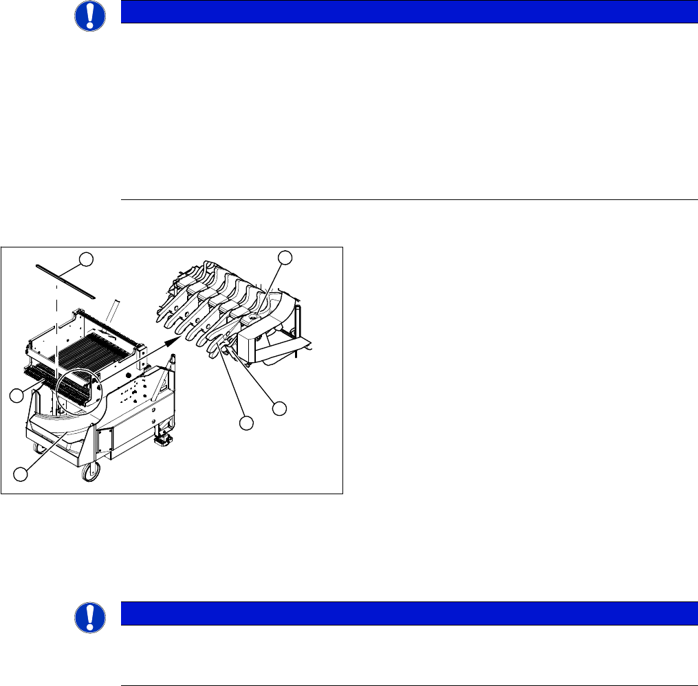
Overview
Removal/installation
► Remove the waste tape container (1) and empty it.
► Refit the waste tape container. This makes sure that any parts which fall down are not lost.
► Loosen the screws fastening the cover plate locking rail [03077142-xx] (2). Use a suitable Phillips
screwdriver, to avoid damaging the screws.
NOTICE
Component trolley X/SX series
Component trolleys from the X series (S) and SX series require a locking latch for each feeder
track.
► X series (S), SX4: feeder lock [03023777-xx] with 40 locking latches
(1x per component trolley X series (S)/SX4)
► Feeder lock [03057284-xx] with 30 locking latches
(1x per 30 track, 2x per 60 track component trolley SX1/SX2)
⇨ The feeder lock can also be completely dismantled from the component trolley and re-
placed.
1. Waste tape container
2. Cover
3. Position of complete feeder locking mechanism
4. Locking latch
5. Tension spring
6. Pressure plate
4
6
5
1
3
2
NOTICE
Tape waste container
You can use the waste tape container as a surface on which to place small parts e.g. tension
springs, locking latches etc.
Service Work
X-Series Component Trolley 3.10.3 Replacing the Guide Profile/Entering Guide Feeder
228 Service Manual SIPLACE X Series
► During reassembly, take care to keep the pressure plates in their correct position (4). These are not
symmetrical and will not hold the shaft properly if placed in a certain (incorrect) position.
► When tightening the fastening screws (3), make sure that the pressure plates (4) are not at an incor-
rect angle and that the locking latches do not jam.
► Hook the tension springs (1) back up.
► Refit the cover.
3.10.3
3.10.3 Replacing the Guide Profile/Entering Guide Feeder
Replacing the Guide Profile/Entering Guide Feeder
Parts, equipment and tools
▪ Guide profile [03002898-xx]
or
Entering guide feeder [03039368 -xx]
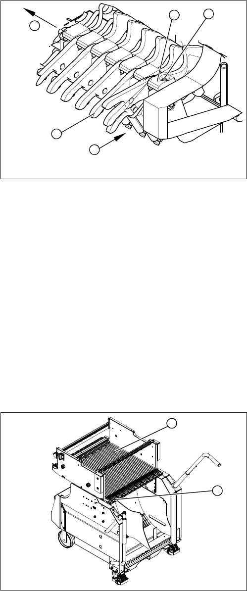
Overview
► Unhook all tension springs (1) from the locking latch-
es (2).
► Loosen the screws (3) fastening the pressure plates
(4).
► Pull out the locking latches with the shaft (5).
► The locking latches can now be pushed off the shaft.
► Return the locking latches, including the new one, to
the shaft.
► Fit the locking latches and shaft.
4
5
1
3
2
1. Short guide profile
2. Entering guide feeder
The guide profiles are fixed from above, with one screw
each.
The feeder entering guide is fixed from below, with three
screws each.
1
2