00194440-10_SM_X-Series_Customer_en.pdf - 第139页
Service Work 3.4.6 Checking the Cable Routing Placement heads Service Manual SIPLACE X Series 139 3.4.6.2 3 . 4 . 6 . 2 X G a n t r y C a b le R o u t in g X Gantry Cable Routing 3.4.6.3 3 . 4 . 6 . 3 C o m p o n e n t S…
Service Work
Placement heads 3.4.6 Checking the Cable Routing
138 Service Manual SIPLACE X Series
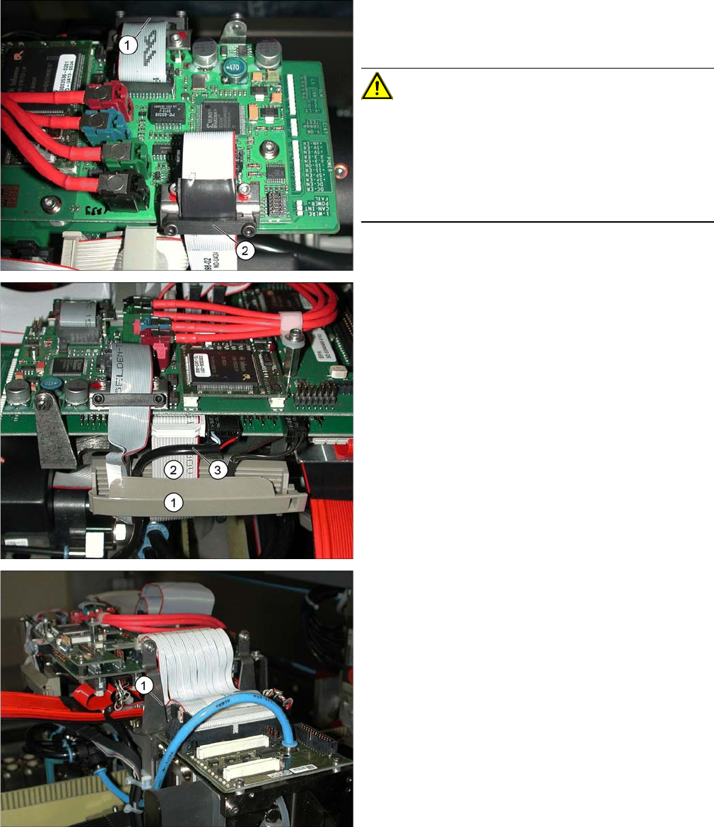
Fixture clamps
▪ The camera cables need to be fastened with fixture
clamps before the connector plugs.
CAUTION!
Do not pinch the cables!
If the camera cable is pinched at the side and damaged,
this could lead to a short circuit (40V) and, for example,
could damage the DC/DC converter.
Always fix cables with a clamp in the middle (2). Do not
overtighten the screws of the fixture clamp.
▪ Check that the clamps are fixed properly at points (1)
and (2).
Securing the connector strip with a cable clamp
▪ To ensure reliable connections, use a cable clamp
(1).
▪ Inside the cable clamp, the cables should be run next
to one another, see also items (2), (3).
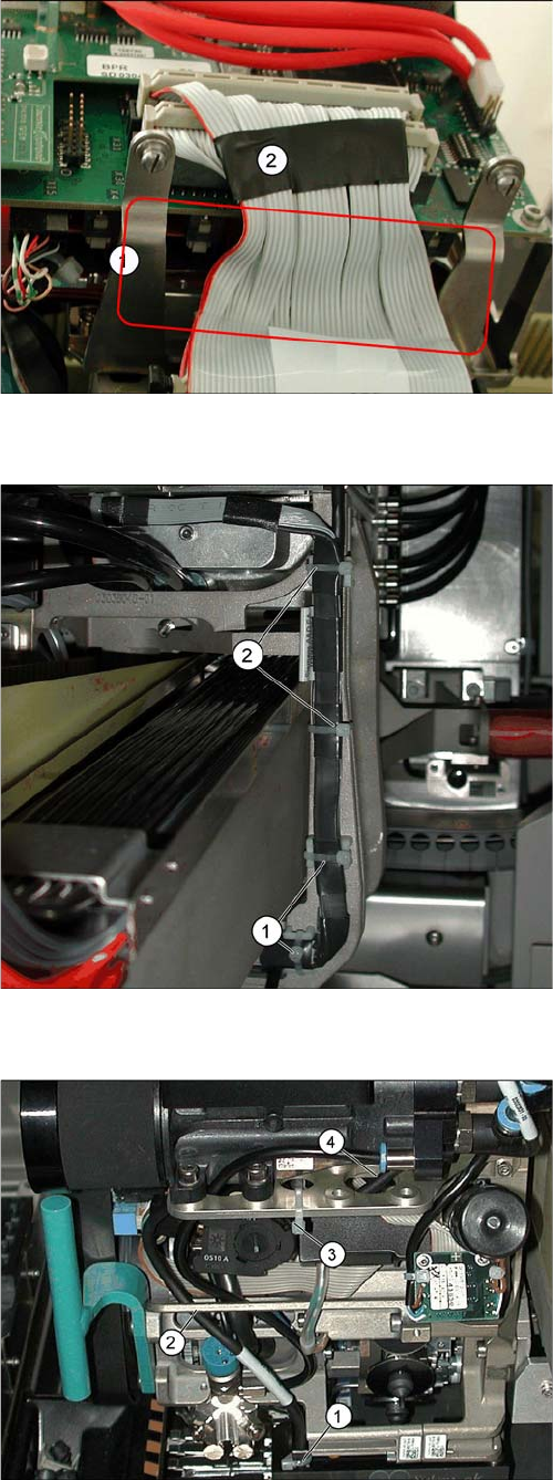
Avoid damage from old supporting plates
▪ Old supporting plates have a gap which is too narrow
for the flat ribbon cable. This could lead to the flat rib-
bon cable insulation being damaged.
▪ If the flat ribbon cable rubs against the supporting
plate, see item (1), either replace the supporting plate
or reduce the width of the flat ribbon cable according-
ly in the vicinity of the gap (2).
Service Work
3.4.6 Checking the Cable Routing Placement heads
Service Manual SIPLACE X Series 139
3.4.6.2
3.4.6.2 X Gantry Cable Routing
X Gantry Cable Routing
3.4.6.3
3.4.6.3 Component Sensor Cable Routing
Component Sensor Cable Routing
Reducing the width of the flat ribbon cable
▪ The width of the flat ribbon cable can be reduced
around the gap (1) by using a wide heat-shrinkable
sleeve or insulating tape (2).
▪ If the flat ribbon cable is damaged, replace it.
In this case, use the "Cable /S-D placement head"
[03047845-xx].
Avoid damage from the Y gantry.
Make sure that the X gantry cables do not touch the Y
gantry.
Four cables ties (1), (2) protect the cables from damage
caused by the Y gantry.
Always use small cable ties, which do not rub against the
gantry.
Avoid loose cables.
The connection cables for the component sensor must be
fixed with a cable tie near to the press-fit connection, as
shown at (1).
The cable is run through the frame openings (2) and (4).
The cable is held by a cable tie at (3).
Service Work
Placement heads 3.4.7 Replacing Stationary Component Camera Digital Type 25/33/36
140 Service Manual SIPLACE X Series
3.4.6.4
3.4.6.4 Running the Valve Positioning Drive Cables
Running the Valve Positioning Drive Cables
3.4.7
3.4.7 Replacing Stationary Component Camera Digital Type 25/33/36
Replacing Stationary Component Camera Digital Type 25/33/36
Refer to the appropriate assembly instructions:
X series, SX series, D3 and D1:
▪ Assembly Instructions Stationary Camera 25 (FC) [00194554-xx] (German and English)
▪ Assembly Instructions Stationary Camera Type 33/36 (IC) [00196608-xx] (German and English)
X Series S:
▪ Assembly Instructions Stationary Camera type 25/33 [00197397-xx] (German and English)
See also
3.7.1 Replacing the X-Series COT Insert [03015680-xx] [ ➙ 195]
5.6.6 DIP Switch for Camera Types 25 and 33 [ ➙ 357]
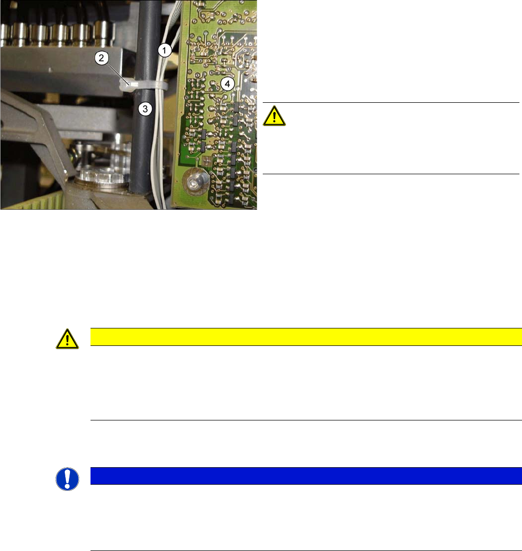
Avoid loose cables.
The diagram shows the board support to the side of the
placement head and the illumination board (4) on the
component camera.
The connection cables for the valve positioning drives (1)
of the reject and placement circuits need to be fixed at the
bolt of the board holder (3) with a cable tie (2).
CAUTION!
Wrap insulating tape around bare bolts
If the bolts are not already covered with a plastic hose, as
shown here, wrap insulating tape around the fixture point.
CAUTION
Risk of injury with cameras of type 25
A heavy mark caul is mounted with the same fixture screws for cameras of type 25. This mark
caul is otherwise only held by the locating pins. If this mark caul falls down, it could cause inju-
ries.
► Make sure that this mark caul is not pulled off the locating pins.
NOTICE
Camera adaptor
You may need to fit an IC camera adaptor assembly. (See the assembly instructions)
► Location 1 to 3: IC camera adaptor assembly SX4a [03099054-xx]
► Location 4: IC camera adaptor assembly SP4 SX4a [03099004-xx]