00194440-10_SM_X-Series_Customer_en.pdf - 第160页
Service Work Modular PCB Conveyor System 3.6.6 Repla cing the Toothed Belt of the Drive Unit [00355553-xx] 160 Service Manua l SIPLACE X Series Installation ► Install the shim/washer (7) and the circlip (8) . ► Loosely f…
Service Work
3.6.6 Replacing the Toothed Belt of the Drive Unit [00355553-xx] Modular PCB Conveyor System
Service Manual SIPLACE X Series 159
3.6.6
3.6.6 Replacing the Toothed Belt of the Drive Unit [00355553-xx]
Replacing the Toothed Belt of the Drive Unit [00355553-xx]
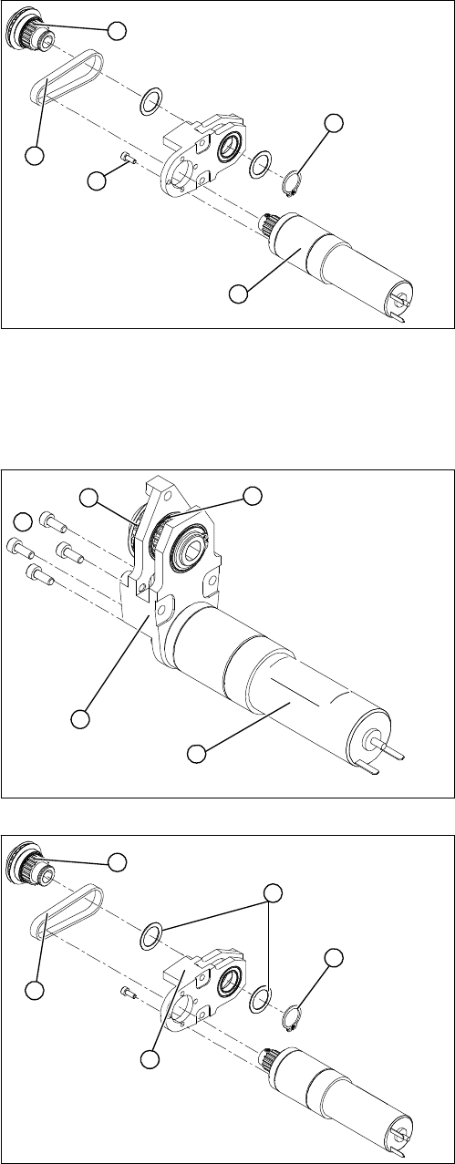
Overview
Removal
► Remove the drive unit as described in "3.6.2 Replacing the Complete Drive Unit [00359284-xx]"
[ ➙ 152].
1. DC geared motor
2. Circlip
3. Four fastening screws
4. Toothed belt
5. Toothed disk
The DC geared motors, including the motor mounts of all
five conveyor areas, are of like construction. Please bear
in mind the following differences during assembly and
disassembly:
▪ The motor mount is installed at an angle (tilted), ac-
cording to the requirements of the installation site.
1
5
4
3
2
► From the outer side of the conveyor, undo the fixtures
holding (2) the DC geared motor (1).
► Tilt the DC geared motor (1) with its toothed disk (4)
a little, so that the small toothed belt comes free of the
toothed disk.
► Pull the DC geared motor out.
► Please observe: the toothed disk on the motor shaft
must be moved out in such a manner that it does not
get caught in the toothed belt.
► Remove the circlip (1) and the shims/washers (2).
► Use a small rubber mallet to carefully knock the
toothed disk (3) out of the motor mount (5).
► Remove the toothed belt (4) from the mount.
5
1
4
3
2
1
5
4
3
2
Service Work
Modular PCB Conveyor System 3.6.6 Replacing the Toothed Belt of the Drive Unit [00355553-xx]
160 Service Manual SIPLACE X Series
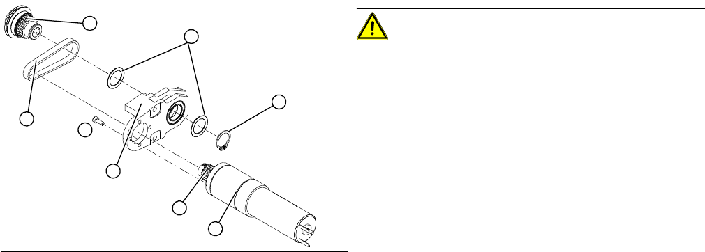
Installation
► Install the shim/washer (7) and the circlip (8).
► Loosely fasten the DC geared motor (5) with the four M3 hexagonal socket-head screws (6). The
entire width of the toothed belt must engage at the top and bottom toothed disks.
► Tension the toothed belt (1) by moving the DC geared motor in the fastening holes. The belt tension
must be between
10 and 15 N.
► Fit the drive unit as described in "3.6.2 Replacing the Complete Drive Unit [00359284-xx]" [ ➙ 152].
CAUTION!
Do not damage the toothed belt!
The toothed belts must not be stretched or kinked!
► Insert the new toothed belt (1) into the motor mount
(2) and place the belt around the toothed disk (3) of
the geared motor.
► Place the toothed belt around the toothed disk (4) of
the conveyor toothed belt and insert the toothed disk
in its mount.
► Use a rubber mallet to carefully knock the toothed
disk into position.
6
8
7
1
5
4
3
2
Service Work
3.6.7 Replacing the Conveyor Toothed Belt (2.5 mm Width) Modular PCB Conveyor System
Service Manual SIPLACE X Series 161
3.6.7
3.6.7 Replacing the Conveyor Toothed Belt (2.5 mm Width)
Replacing the Conveyor Toothed Belt (2.5 mm Width)
3.6.7.1
3.6.7.1 Replacing the Conveyor Toothed Belt (ET/DT)
Replacing the Conveyor Toothed Belt (ET/DT)
Parts
For item numbers and the designation of the respective toothed belt, please refer to the spare parts cat-
alogue.
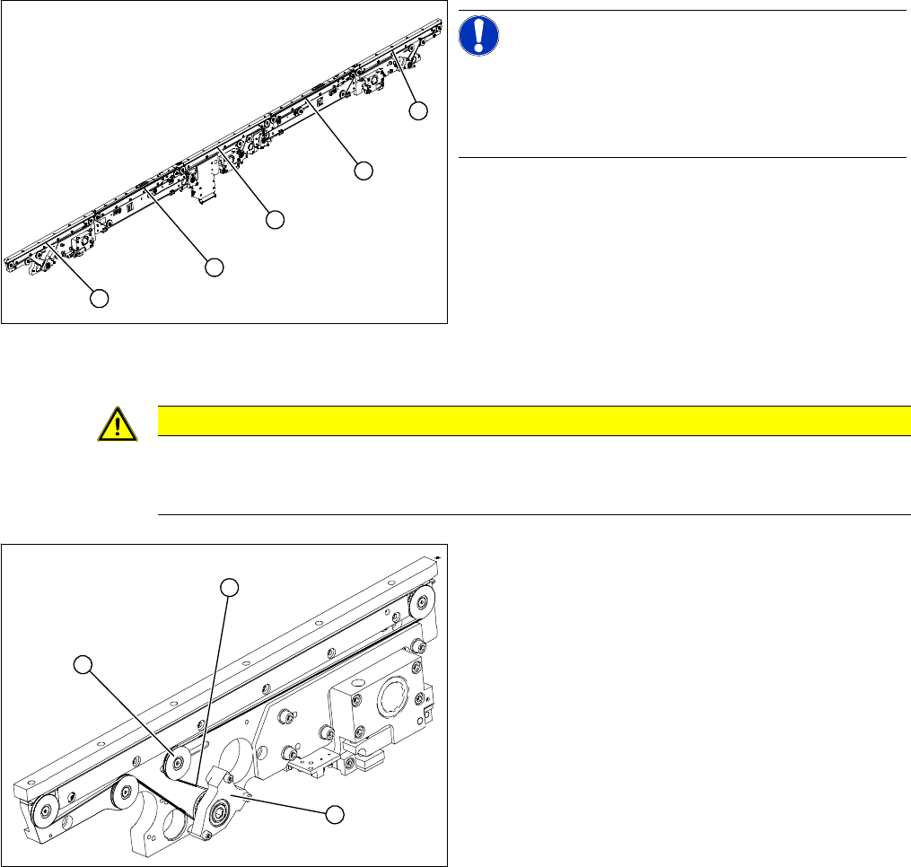
Overview
Removal
► Move the PCB conveyor to the position which gives you best access to the conveyor belt
► Move the Y gantries into the area outside the PCB conveyor.
► Switch off the machine and secure it to prevent unauthorized reactivation.
NOTICE!
The following diagrams apply to the standard conveyor
system (fixed side - right). Depending on the conveyor
edge (right or left) either the mount or the drive unit will be
fitted.
1. Input conveyor
2. Placement area 1
3. Intermediate conveyor
4. Placement area 2
5. Output conveyor
1
5
4
3
2
CAUTION
Do not damage the toothed belt!
The toothed belts must not be stretched or bent!
The minimum radius of the toothed belt is 16 mm.
1. Tape drive (mount)
2. Deflection pulley with slot
3. Conveyor toothed belt
The way in which the conveyor toothed belt is run around
the deflection pulley depends upon the transport area
concerned. Please observe this belt guidance during as-
sembly and disassembly. Please also bear in mind the
following differences during assembly and disassembly:
▪ The drive unit is installed at an angle (tilted), accord-
ing to the requirements of the installation site.
▪ Depending on the conveyor cheek, either the tape
drive (mount) or the DC drive motor will be installed.
1
3
2